

How Do You Validate a 3D Scanner Wand for Industrial On-Site Inspection?
3d scanner wand: The Unique Inspection Challenge of On-Site Dimensional Verification for Complex Parts The Unique Inspection Challenge of On-Site Dimensional.
The Unique Inspection Challenge of On-Site Dimensional Verification for Complex Parts
When a dimensional inspection workflow moves from the climate-controlled metrology lab to the factory floor, an MRO hangar, or a field service site, the entire definition of “routine measurement” changes.
A part that was easy to fixture on a granite CMM during design validation becomes a different problem entirely when it is bolted to an aircraft wing, welded into an assembly line, or sitting in a maintenance cradle two meters off the ground.
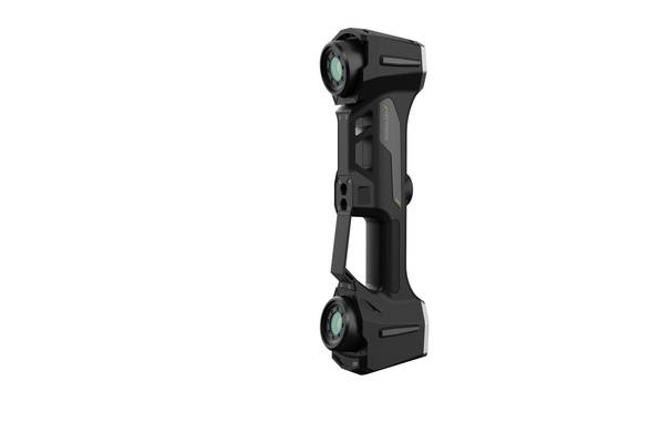
Teams evaluating a 3D scanner wand are typically responding to one core task: capturing dimensional data from large, immovable, or hard-to-access parts without moving them to the instrument.
Deployment Validation Checklist
| Focus Area | Decision Point | Deployment Note |
|---|---|---|
| Target part | Check size, surface condition, and key tolerances against the scan task | Run a full trial scan on a representative part |
| Data workflow | Verify point cloud, deviation map, and quality-report handoff | Confirm export formats and review ownership in advance |
| Shop-floor use | Review training, calibration, lighting, and working space | Keep the validation record as a repeatable inspection reference |
Practical Workflow
- The Unique Inspection Challenge of On-Site Dimensional Ve… — When a dimensional inspection workflow moves from the climate-controlled metrology lab to the factory floor, an MRO hangar, or a…
- Key Application Constraints to Diagnose Before Evaluating… — What does it actually take to inspect a part without moving it?
- Common Capture Risks That Compromise Handheld 3D Scan Dat… — How often do you rework a scan because a section shifted out of alignment and nobody caught it until the mesh was already merged?
- Matching 3D Scanner Wand Capabilities to Your Diagnosed R… — One of the most persistent misconceptions in industrial measurement is that higher accuracy claims on a spec sheet translate dire…
That task shows up across Western industrial sectors in predictable patterns. Aerospace MRO teams need to verify wear, distortion, or blend-repair geometry on engine nacelles and flight control surfaces without removing components from the aircraft. Automotive OEM tooling groups check fixture and die geometry between production runs, often inside cells where a bridge CMM cannot reach.
Energy service providers inspect turbine blades and casings during outage windows, where time on-site is measured in hours and disassembly is expensive. Medical device manufacturers validate custom implants and surgical guides against patient-specific CAD data, where every surface deviation carries clinical weight.
The measurement requirements in these environments are not relaxed simply because the part cannot come to the lab. Regulated industries still require alignment with ASME GD&T callouts and verification workflows that respect ISO 10360 principles for measurement system performance.
The difference is that the data must now be captured in place, under ambient conditions, by personnel who may not be dedicated metrology specialists, and delivered in a format that quality engineering can use for first-article inspection, root-cause analysis, or customer-facing documentation.
A solution engineer approaching this problem should diagnose fit before purchase. That means understanding not just the scanner specifications, but the physical access constraints, the required data deliverable, the alignment strategy, and the validation path for proving that the captured data is trustworthy.
The sections that follow break down that diagnostic process into the practical questions that matter most on the plant floor.
Key Application Constraints to Diagnose Before Evaluating Any Handheld Scanning Tool
What does it actually take to inspect a part without moving it? Before anyone on your team evaluates a handheld 3D scanner wand, you need to walk through six constraints that decide whether a given application will work line-side or only in a lab.
Part geometry is the first filter. Deep cavities, undercuts, and free-form surfaces defeat calipers and height gauges quickly. Fixed CMMs can reach some of these features, but only if you bring the part to the machine. That breaks takt time.
Material properties matter just as much. Reflective metal, carbon fiber composite, and translucent polymer each create data-quality problems for stationary structured light scanners. If the surface finish changes between batches, your repeatability changes with it.
Tolerance bands set the real bar. Safety-critical parts with tight dimensional callouts leave no room for a scanner that drifts between setups. You need to know whether the tool holds accuracy across the full working volume, not just in a controlled demo.
Site environment is where many evaluations fail. Dust, variable lighting, limited working space, and temperature swings between shifts all affect capture stability. A system that works in a metrology lab may struggle next to a machining cell.
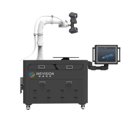
Production takt time is the final constraint. If line-side inspection windows are measured in minutes, moving parts to a controlled lab for every check creates a bottleneck. Traditional methods force that move. A handheld scanner wand changes the workflow only if it can capture, align, and validate within the window you actually have.
INSVISION designs its industrial 3D scanning tools around these field constraints, but the diagnostic work has to come first.
Common Capture Risks That Compromise Handheld 3D Scan Data Integrity
How often do you rework a scan because a section shifted out of alignment and nobody caught it until the mesh was already merged? It happens more than most teams want to admit.
Four risks account for most invalidated handheld 3D scanner wand datasets. The first is alignment drift. When an operator moves between part sections without enough consistent reference geometry, the software gradually loses its lock. Small angular errors compound. By the time the scan is complete, the point cloud no longer reflects the physical part. The second risk is missed geometry in hard-to-reach areas.
Restricted scan angles and limited depth of field leave shadow zones near bosses, deep pockets, or undercuts. Those voids often sit exactly where the tightest GD&T callouts live. The third is inconsistent point cloud density. If surface coverage varies too much, tolerance reporting becomes unreliable. You cannot defend a first-article inspection when the data behind a critical bore is sparse.
The fourth is unplanned rescan cycles. Once a part leaves the fixture, bringing it back for another pass takes time you do not have inside a takt window.
Each failure mode pushes quality reports later, blocks part release, and raises exposure to non-conformance penalties in regulated sectors. INSVISION designs its industrial 3D scanner workflows around these failure points. For example, the industrial 3D scanner configuration offers up to 0.020 mm scanner accuracy and a 650 mm depth of field, which helps operators maintain consistent reference coverage across larger zones.
That reduces alignment drift and cuts the odds of a late rescan. Even with capable hardware, the process still matters. Locking down fixture references, validating density before export, and scheduling a short pre-release audit are the habits that keep scan data defensible.
Matching 3D Scanner Wand Capabilities to Your Diagnosed Requirements
One of the most persistent misconceptions in industrial measurement is that higher accuracy claims on a spec sheet translate directly into better inspection outcomes. In practice, a 3D scanner wand that cannot hold alignment inside a deep cavity, or that forces an operator into an awkward posture for forty minutes, will undercut even the most impressive laboratory accuracy figure.
Matching a 3D scanner wand to diagnosed requirements starts with the tolerance stack, not the marketing number. If a first-article inspection allows ±0.050 mm on critical GD&T callouts, then a system rated up to 0.020 mm provides useful margin without chasing unnecessary cost. Scan area and depth of field matter just as much.
A wand with limited depth of field forces multiple rescan passes on contoured castings, which multiplies alignment error and operator fatigue. Ergonomic access, dust resistance, and direct export into existing CAD and quality management software determine whether the tool gets used daily or parked in the lab.
INSVISION builds industrial-grade 3D scanner wands around these on-site constraints, treating accuracy as one variable inside a broader inspection workflow rather than an isolated selling point.
A Practical Validation Checklist for Pre-Purchase Testing
Are you actually validating the scanner for your process, or just checking the spec sheet? Most teams skip the hard part. They compare accuracy numbers in a conference room, then find out on the shop floor that the system does not fit the workflow. A practical pre-purchase test changes that.
Start with alignment accuracy. Bring a calibrated reference artifact and measure it under the same environmental conditions the scanner will see in production. Temperature swings, vibration, and ambient light affect optical systems. If the scanner cannot hold tolerance on a known artifact in your real environment, the catalog number means nothing.
This approach aligns with ISO 10360 validation principles for industrial measuring equipment.
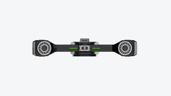
Next, scan a representative production part. Not a simple prismatic block. Pick a part with undercuts, cavities, or deep pockets. Can the 3D scanner wand capture the full geometry in a single pass, or does the operator need multiple setups and stitching? Every additional pass adds time and error.
For an INSVISION industrial 3D scanner, this test reveals whether the scanning area and depth of field match your actual part envelope.
Data compatibility is where procurement often gets burned. Export the scan data from the test part. Open it in your existing inspection software. Check the mesh density, file format, and any conversion steps required. If your quality team needs STL or point cloud data in a specific coordinate system, verify that the exported file loads cleanly without manual repair.
Then measure total inspection time. From part setup to final report, time the full sequence. Compare that against your takt window. A scanner that is technically accurate but takes three times longer than your current method will not survive on the line. This step matters more than the headline accuracy specification.
Finally, assess ease of use for frontline technicians. Have a technician who has never used the system run the test. How long before they produce usable data? Training time is a direct labor cost. If the interface requires a specialist to operate, your total cost of ownership changes significantly.
This checklist works because it ties the purchase decision to your process, not to a vendor demo. You avoid overbuying a system with capabilities you do not need, and you avoid underbuying a scanner that cannot handle the geometry or environment.
Use Case Boundaries: Where 3D Scanner Wands Deliver the Strongest Value
The shift toward portable metrology has changed how manufacturers handle large, immovable parts. Ten years ago, a turbine housing or weldment inspection meant moving the part to a CMM or building a dedicated fixture. That cost time and introduced handling risk. Today, a 3D scanner wand allows teams to bring measurement directly to the part, which matters when the component weighs several tons or is already installed on-site.
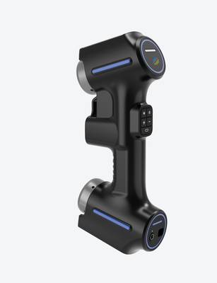
This section defines where a handheld 3D scanner wand delivers the strongest operational value. The key is matching the tool to the task. For on-site inspection of large castings, field service checks on energy equipment, or MRO reverse engineering of legacy parts without CAD data, the wand approach reduces staging labor and shortens the data capture window.
Low-volume, high-mix production also benefits because setup time drops compared to hard gauging.
High-volume inline inspection, by contrast, often favors automated or fixed scanning cells, where repeatability and integration with conveyance systems drive the decision. INSVISION provides both portable and automated industrial 3D scanning solutions, so the selection should follow the production environment rather than forcing one tool into every scenario.
Hangzhou Insvision Technology Co., Ltd.
Address: Building 1, No. 1399 Liangmu Road, Yuhang District, Hangzhou, Zhejiang 311121, China
Copyright © Hangzhou Insvision Technology Co., Ltd. All rights reserved.
Copyright © Hangzhou Insvision Technology Co., Ltd. All rights reserved.