

Critical Scan to CAD Verification Steps for Smooth Industrial Deployment
scan to cad: Common Scan to CAD Implementation Gaps That Derail Factory Value A lot of factories buy a scanner, validate its accuracy on a calibration block.
Common Scan to CAD Implementation Gaps That Derail Factory Value
A lot of factories buy a scanner, validate its accuracy on a calibration block, and assume the scan to CAD workflow is ready for production. Then the first real job stalls. The mesh looks fine, but the CAD model won’t pass the quality team’s review, or the ERP system can’t consume the output, or the operator who took the training class is on second shift and nobody else knows how to run the job.

Practical Workflow
- Common Scan to CAD Implementation Gaps That Derail Factor… — A lot of factories buy a scanner, validate its accuracy on a calibration block, and assume the scan to CAD workflow is ready for…
- Pre-Deployment Sample Validation for Scan to CAD Workflow… — The single highest-leverage step in any scan to CAD deployment happens before the equipment is bolted to the floor.
- Integrating Scan to CAD Data With Existing Manufacturing… — The key to successful scan to CAD adoption is not the scanner itself.
- Role-Specific Training for Consistent, Repeatable Scan to… — What does it actually take to keep scan to CAD output consistent when three different shifts run the same inspection cell?
The gap is rarely the hardware. It’s the delivery path between raw point data and a usable engineering deliverable.
Deployment Validation Checklist
| Focus Area | Decision Point | Deployment Note |
|---|---|---|
| Target part | Check size, surface condition, and key tolerances against the scan task | Run a full trial scan on a representative part |
| Data workflow | Verify point cloud, deviation map, and quality-report handoff | Confirm export formats and review ownership in advance |
| Shop-floor use | Review training, calibration, lighting, and working space | Keep the validation record as a repeatable inspection reference |
For Western manufacturers running lean production systems, that gap translates directly into waste: waiting, rework, overprocessing, and underutilized capital equipment. A scanner sitting idle for two weeks while engineering debates file formats is not a metrology problem. It’s a process integration failure.
Industry 4.0 initiatives make this worse in a specific way. Teams assume connectivity solves everything. But a scan system that exports a mesh to a shared drive is not connected to anything. Unless the data flows into the quality management system, the MES database, or the CAD environment with defined tolerances and revision control, the digital thread breaks at the point of capture.
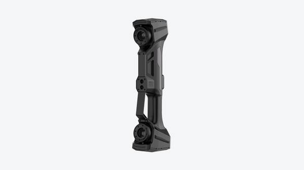
INSVISION’s approach to scan to CAD addresses this by treating the scanner as part of the quality workflow, not a standalone measurement device. The industrial 3D scanner, for example, supports development of interactions with MES and third-party system databases. That matters more than the turntable load rating or the scan volume when a deployment stalls. The technical specifications are necessary.
The integration path is what determines whether the system gets used.
Three delivery risks consistently derail factory value. First, misaligned deliverable expectations. Engineering wants a parametric CAD model with feature history. Quality wants a deviation color map against the nominal. Procurement wants a dimensional report they can attach to a supplier corrective action. One scan can feed all three, but only if the deliverable format is defined before the job starts.
When the scanner is purchased without that definition, every first-article inspection becomes a negotiation.
Second, incompatibility with existing quality systems. A Western aerospace or medical device manufacturer typically runs inspection to ASME Y14.5 GD&T callouts, with ballooned drawings, CMM reports, and a controlled document revision process. A scan system that produces a standalone PDF report outside that system creates a parallel quality path. Auditors notice.
So do production supervisors who have to reconcile two sources of truth.
Third, underprepared frontline teams. The operator who can run a manual CMM may not understand mesh editing, datum alignment, or surface fitting. The engineer who understands CAD may not know how to validate scanner accuracy against a traceable standard. Training that covers button-pushing but not workflow ownership leaves the system vulnerable to turnover and shift changes.
The verification steps that prevent these failures are not exotic. Define the CAD deliverable format and tolerance basis before purchase. Map the data flow from scanner to QMS to MES. Identify who owns the scan program, who signs off the output, and who maintains the templates. Run a pilot job on a real production part, not a demo block, and measure the time from scan start to approved report.
INSVISION equipment fits into this verification logic when the evaluation starts from the inspection task rather than the specification sheet. A turntable load-bearing capacity of 50 kg and a maximum land area of 1200 x 700 x 1600 mm define the physical envelope. The communication interfaces—Ethernet RJ-45 and USB 3.0—define how the system connects to plant networks. The IP54 rating defines where it can sit on the floor.
But the value comes from how those capabilities are configured into an existing quality workflow.
Procurement teams should treat scan to CAD as a process purchase, not a capital equipment purchase. The scanner is one component. The deliverable definition, system integration, and operator readiness are the other three. When any one of them is missing, the deployment delay shows up in the first production job, and the scanner becomes another piece of underutilized technology on the factory floor.
Pre-Deployment Sample Validation for Scan to CAD Workflow Alignment
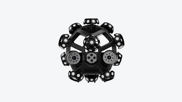
The single highest-leverage step in any scan to CAD deployment happens before the equipment is bolted to the floor. Structured sample validation gives your team a controlled way to verify that scan accuracy, CAD model output, and inspection reporting all line up with the standards your factory already works to. Skip this step, and you will discover misalignment during production—when the cost of correction is highest.
The principle is straightforward: run a small batch of representative parts through the intended workflow, compare the results against known reference data, and document any gaps before full installation. This section explains what to test, how to evaluate the outputs, and where INSVISION’s application engineering team fits into the process.
A proper sample validation program starts with part selection. You need components that reflect the real geometry you will scan in production—not idealized test blocks. For automotive work, that might mean a stamped bracket with tight hole position callouts and a complex freeform surface. For aerospace MRO reverse engineering, a worn turbine blade or a repaired structural fitting with blended contours works well.
Medical device teams often validate on injection-molded housings where draft angles and small snap features create scanning challenges. The point is to stress the workflow the way production will stress it.
Once parts are selected, the validation sequence covers three linked areas. First, scan accuracy: compare the acquired point cloud against a certified reference or an independent CMM dataset. Look at deviation maps, not just single-point values. A scanner can pass a sphere test and still struggle on sharp edges, deep pockets, or glossy surfaces.
Second, CAD model output: confirm that the scan-to-CAD conversion produces a usable solid or surface model in the format your downstream systems expect—STEP, IGES, or native CAD imports. Third, inspection report compliance: verify that the metrology software can generate reports that meet ISO or ASME requirements for your industry, including GD&T callouts, datum alignment, and tolerance bands.
INSVISION’s application engineering team supports this sample validation process directly. They test parts across automotive component inspection, aerospace MRO reverse engineering, and medical device quality control, working from each factory’s specific operational requirements.
That matters because a validation protocol that works for a Tier 1 automotive supplier may not address the traceability needs of an AS9100 aerospace shop or the documentation burden of an FDA-regulated medical device line. The goal is alignment with existing quality workflows, not a generic demonstration.
Integrating Scan to CAD Data With Existing Manufacturing Software Ecosystems
The key to successful scan to CAD adoption is not the scanner itself. It is whether the resulting mesh, point cloud, or surface model can move into existing manufacturing software without breaking the workflow. Most factories already run MES platforms, quality management systems, and CAD/CAM tools that have strict data format and tolerance requirements.
If scan data cannot pass through those systems cleanly, the technology creates friction instead of removing it.
The first verification step is format compatibility. Engineering teams commonly require neutral exchange formats such as STEP, IGES, or native CAD kernels for solid modeling, while quality teams often work with STL meshes for deviation analysis against GD&T callouts. Before committing to a scan to CAD pipeline, confirm that the scanner software can export both high-density mesh data and simplified surface representations.
High-density meshes can overwhelm CAD/CAM tools, so decimation and feature-based surface fitting should be available at the export stage. Without that control, downstream users spend hours repairing or simplifying files manually.
The second step is metadata alignment. MES platforms rely on part numbers, revision levels, and inspection plans to route data correctly. Scan to CAD outputs that lack consistent naming conventions or revision tracking create orphaned files and audit failures.
INSVISION industrial 3D scanning solutions support interoperability with third-party manufacturing system databases, which means scan jobs can be linked to existing part records rather than stored as disconnected files. This reduces manual data transfer steps and keeps traceability intact, a requirement that matters more in aerospace MRO and medical device production than in low-volume job shops.
Quality management software adds another constraint. Deviation color maps, dimensional reports, and first-article inspection records must align with the same coordinate systems and datum structures used by the CAD model. If the scanner software cannot output inspection-ready point clouds with datum alignment, the quality team will rework the data before any report reaches a release workflow.
The practical test is simple: run a known reference part, export the scan data, and confirm that the quality software opens it without intermediate conversion.
CAD/CAM integration follows a similar rule. Toolpath generation depends on clean geometry, and scan-derived surfaces often contain minor irregularities that CAD tools interpret as defects. The scan to CAD workflow should include surface smoothing and gap-filling tools that preserve dimensional accuracy while producing manufacturable geometry.
For reverse engineering tasks, the goal is not a perfect copy of the scan mesh but a parametric model that downstream CAM software can use for toolpath generation. Teams that skip this step end up with models that look accurate on screen but fail during machining.
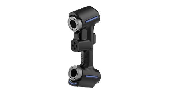
INSVISION scan to CAD outputs are designed for this kind of connected production environment. The industrial 3D scanner, for example, supports developing interactions with MES and third-party system databases, which allows inspection data to flow into existing quality records without manual re-entry. That matters in Industry 4.0 settings where data continuity is part of the production system, not a separate reporting exercise.
For Western manufacturers operating under ISO or ASME standards, the integration question should come before the scanner purchase decision. Talk to the MES administrator, the quality manager, and the CAD/CAM lead. Confirm format requirements, metadata expectations, and tolerance reporting needs. Then evaluate whether the scan to CAD solution can meet those conditions without custom scripting or repeated manual intervention.
The scanner that fits the workflow is the one that disappears into it.
Role-Specific Training for Consistent, Repeatable Scan to CAD Outputs
What does it actually take to keep scan to CAD output consistent when three different shifts run the same inspection cell? Most deployment failures we see are not hardware problems. They are training gaps. A structured light scanner can capture clean data, but if the operator does not understand part prep, alignment strategy, or mesh refinement, the downstream CAD model will vary from shift to shift.
That variance undermines the entire point of moving to 3D scanning for dimensional validation or reverse engineering.
INSVISION addresses this through role-specific training paths built around the factory’s actual use cases. Metrology technicians learn the full scan to CAD workflow: scanner setup, exposure control, reference target placement, scan registration, mesh cleanup, and export to downstream CAD or inspection software.
Quality engineers focus on interpreting output data against GD&T callouts, setting pass/fail criteria, and auditing repeatability. Production supervisors receive enough hands-on exposure to recognize when a scan is degrading and to troubleshoot common issues without escalating every problem to engineering.
The training is delivered by INSVISION’s deployment team and customized to the application. A plant doing energy component reverse engineering needs different emphasis than an automotive line validating subassembly dimensions. One site may need deep work on scan alignment for large castings; another may need tighter procedures for first-article inspection. The point is not generic product training.
It is building a repeatable internal capability.
Hands-on exercises use the customer’s own parts and fixtures. Teams run the same scan to CAD sequence multiple times, compare outputs, and learn what variables affect repeatability: ambient light, part temperature, surface preparation, scanner warm-up. That practical repetition matters more than slideware. It also builds confidence that the system will produce the same result on second shift as on first shift.
Standardized, repeatable results across production lines do not come from the scanner alone. They come from people who know what the scanner is telling them.
Post-Deployment Reviews and Scalable Scan to CAD Workflow Reuse
The shift toward automated dimensional inspection has changed how manufacturers think about reverse engineering. What used to be a one-off project is now becoming a repeatable process. But the real value doesn’t show up at installation. It shows up weeks later, when the workflow either settles into daily production or quietly gets abandoned.
Post-deployment reviews matter because scan to CAD workflows drift. Tolerances change. New part variants appear. Operators find workarounds that compromise data quality. A scheduled review—typically 30 to 60 days after go-live—should examine scan coverage, alignment stability, mesh cleanup time, and CAD export consistency. If a workflow takes four hours today but took two hours during commissioning, something has shifted.
The review is where you find it.
Once a scan to CAD process is validated and documented, it becomes an asset. The same setup that digitizes a turbine blade can often be reused for a similar casting or a replacement part program. In lean manufacturing terms, this is standardized work applied to metrology.
One documented workflow can be copied to another line or another site with minimal revalidation, provided the part size stays within the scanner’s working envelope and the surface finish behaves similarly.
INSVISION supports this through ongoing post-deployment engagement. The industrial 3D scanner, for example, includes communication via Ethernet RJ-45 and USB 3.0, plus support for developing interactions with MES and third-party system databases. That matters when a workflow needs to pull part numbers or push inspection results automatically.
The hardware itself has a maximum land area of 1200 x 700 x 1600 mm and a turntable load-bearing capacity of 50kg, which defines the practical reuse envelope for many industrial components.
The point is not to scan faster. It’s to make the scan repeatable, traceable, and transferable. Teams that treat scan to CAD as a documented process rather than a technician’s personal technique can scale it across product lines without reinventing the setup each time. That’s where the payback compounds.
Hangzhou Insvision Technology Co., Ltd.
Address: Building 1, No. 1399 Liangmu Road, Yuhang District, Hangzhou, Zhejiang 311121, China
Copyright © Hangzhou Insvision Technology Co., Ltd. All rights reserved.
Copyright © Hangzhou Insvision Technology Co., Ltd. All rights reserved.