

Validated 3D Scanning Accuracy Supports Aerospace Turbine Blade Inspection
3d scanning accuracy: Aerospace MRO Turbine Blade Inspection: Balancing Accuracy and Turnaround Time Aerospace MRO Turbine Blade Inspection: Balancing.
Aerospace MRO Turbine Blade Inspection: Balancing Accuracy and Turnaround Time
Walk into any aerospace MRO cell during a turbine blade inspection bottleneck, and the workflow difference becomes obvious. Traditional tactile inspection often means a CMM programmer building a fixture, setting up a probe path, and capturing maybe a few dozen discrete points per airfoil. The result is metrology-grade data, but the setup cycle can consume hours before the first measurement is even taken.
Hand gauges are faster but leave gaps across curved airfoil sections and internal cooling channel geometry. The before/after shift with a 3D scanning workflow is less about replacing the CMM entirely and more about changing where measurement time goes.
Instead of long fixture setup and point-by-point probing, the operator scans the full blade surface, captures dense point cloud data, and compares it against the OEM CAD model or a golden part reference. For MRO teams balancing airworthiness documentation against turnaround commitments, that shift changes the bottleneck from data collection to data review.
The inspection task itself becomes faster, but the real value is having enough surface coverage to make defensible pass/fail calls on complex features without slowing the entire cell down.
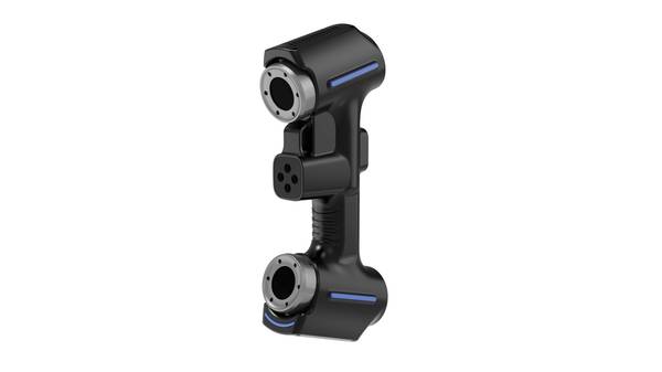
Capability and Deployment Mapping
| Focus Area | Decision Point | Deployment Note |
|---|---|---|
| Aerospace MRO Turbine Blade Inspection: Balancing Accur… | Walk into any aerospace MRO cell during a turbine blade inspection bottleneck, and the workflow difference becomes obvious. | Traditional tactile inspection often means a CMM programmer building a fixture, setting up a probe path, and capturing maybe a few dozen discret… |
| Full-Field 3D Scanning Workflows for Precision Aerospac… | How do you verify an airfoil with enough confidence to sign off on it? | Turbine blade inspection has always been a fight against sampling. |
| Validating 3D Scanning Accuracy for Traceable Aerospace… | As aerospace programs push toward tighter GD&T callouts and digital first-article inspection, the burden on metrology has shifted. | The question is no longer whether a scanner can capture dense surface data, but whether that data will hold up under audit. |
| High-Accuracy 3D Scanning Applications Across Precision… | Aerospace MRO teams have long understood the value of 3D scanning accuracy for wear mapping and reverse engineering. | The same capability now carries weight in other Western manufacturing environments where tolerance stacks leave little room for error. |
Full-Field 3D Scanning Workflows for Precision Aerospace Inspection
How do you verify an airfoil with enough confidence to sign off on it? Turbine blade inspection has always been a fight against sampling. A CMM probes discrete points. You get numbers at those locations. You do not get the surface between them. A local deviation in leading-edge radius, a shallow blend step, a chordwise ripple — those can sit between sample lines and never register.
Full-field 3D scanning changes the question. Instead of checking a few dozen points, you capture the entire surface as point cloud data. The workflow starts with stable fixturing and, when needed, a thin developer spray on reflective or dark coatings. Then the scan proceeds across the airfoil, platform, and root fillet.
Point cloud processing aligns the data to CAD, and the software builds a color map of deviation across every square millimeter.
For aerospace metrology, 3D scanning accuracy is not a marketing term. It is the difference between a report that passes and a report you can defend. When inspection results must align with AS9100 requirements and GD&T callouts, the data foundation has to be dense, repeatable, and traceable. Discrete sampling leaves gaps. Full-field capture leaves fewer places for a non-conformity to hide.
INSVISION’s Multi-Mode Laser Scanning R&D: Engineered for Consistent Accuracy Across Complex Geometries
Aerospace turbine blade inspection has shifted in recent years. Programs that once accepted hard gauging and sectional CMM checks as the default are now under pressure to capture full surface geometry faster, without losing the tight tolerances that make airfoil inspection so unforgiving. The driver is not just throughput.
It is the need to verify more of the blade, more often, and with enough resolution to catch deviation before it reaches downstream assembly or repair.
That shift has pushed manufacturers toward structured light and laser scanning. But the core problem has not gone away: turbine blades are deliberately difficult to measure. They combine thin trailing edges, twisted airfoil curvature, film cooling holes, and deep root geometries in one part. A scanner that handles the airfoil smoothly may struggle inside a cooling hole.
A mode that captures sharp edges may produce noise on curved surfaces. In many shops, the workaround has been multiple scanning systems, multiple setups, or accepting that some features will be measured indirectly.
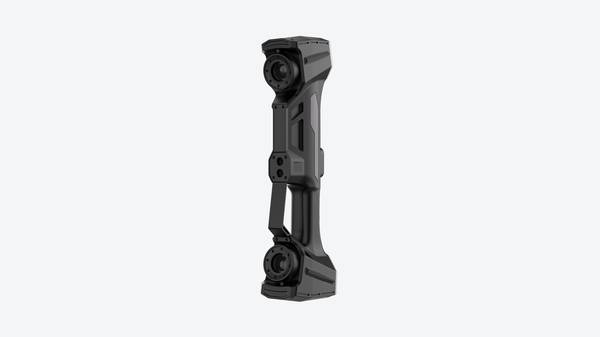
INSVISION has approached this from an R&D angle that targets the measurement problem itself rather than the part category. The company’s in-house multi-mode laser scanning development is built around the idea that one scanning platform should adapt its parameters to different feature types during the same inspection routine.
The engineering relevance to turbine blades is direct: specialized scanning modes can cover deep cooling holes, edge profiles, and curved airfoil surfaces in a single setup. For quality engineers, that reduces the number of handoffs and the chance that a critical feature gets left out of the digital record.
The accuracy question is always present in these discussions. When a scanner switches modes, the concern is whether it maintains measurement consistency. That is where the development focus becomes clear. INSVISION’s multi-mode approach is not simply about offering more laser line configurations. It is about keeping 3D scanning accuracy stable while the scanner moves between feature types.
That matters in aerospace because the same blade may require a tight profile tolerance on the leading edge and a reliable diameter check on a cooling hole, all within one inspection cycle. A scanner that drifts between modes creates more work in validation and correlation studies.
For Western manufacturers working under ASME or ISO frameworks, this kind of capability fits into a broader move toward measurement data that can support first-article inspection, in-process checks, and MRO assessments without rebuilding the inspection plan for every part revision. The value is not in replacing CMMs outright.
It is in giving engineers a faster way to generate dense surface data where CMM probing is slow or impractical, while still producing results that can be compared against existing GD&T callouts and tolerance zones.
Validating 3D Scanning Accuracy for Traceable Aerospace Metrology
As aerospace programs push toward tighter GD&T callouts and digital first-article inspection, the burden on metrology has shifted. The question is no longer whether a scanner can capture dense surface data, but whether that data will hold up under audit. Traceability now drives the conversation.
Validating 3D scanning accuracy for aerospace metrology starts with calibrated reference artifacts. A quality manager typically stages a series of traceable standards—sphere bars, gauge blocks, or certified step gauges—across the scanner’s working volume. The scanner’s measured values are compared against the artifact’s certified dimensions, not against nominal CAD. That distinction matters.
CAD comparison checks form, but artifact comparison checks the instrument itself.
Repeatability and reproducibility testing comes next. Running the same artifact multiple times under unchanged conditions establishes repeatability. Shifting operators, fixtures, or scan orientations establishes reproducibility. In aerospace work, R&R results need to fall well inside the part tolerance band, not just inside it.
If a feature tolerance is 0.100 mm, an R&R spread of 0.040 mm may be statistically acceptable but operationally risky once thermal drift and shop floor vibration enter the picture.
Volumetric accuracy across full part dimensions is the third piece. Large airframe components, engine casings, and structural brackets rarely sit in a single scan window. The scanner must maintain accuracy as data is stitched across long distances. A photogrammetric scale bar helps anchor the point cloud, reducing accumulated error on parts spanning a meter or more.
INSVISION’s industrial scanning systems are built around this workflow, with volumetric accuracy specifications that quality teams can reference when mapping scanner performance to part size.
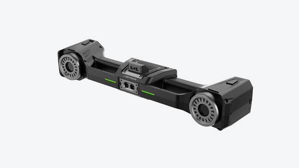
For quality managers, the practical evaluation comes down to three variables. Part size determines whether a scale bar or photogrammetry loop is needed. Feature complexity determines whether the scanner must switch between precision lines and deep-hole scanning modes. Shop floor conditions—temperature swings, vibration, ambient light—determine how often interim verification should run.
INSVISION supports this by providing scanning modes suited to both fine surface detail and hard-to-reach hole geometry, allowing the same validation protocol to extend from the metrology lab to the production cell.
None of this replaces a CMM where a CMM is mandatory. But for large surfaces, freeform geometry, or parts that cannot be fixtured easily, a validated 3D scanning process gives aerospace teams something a CMM cannot: dense, traceable surface data that can be archived, re-audited, and compared across the full part lifecycle.
High-Accuracy 3D Scanning Applications Across Precision Manufacturing Sectors
Aerospace MRO teams have long understood the value of 3D scanning accuracy for wear mapping and reverse engineering. The same capability now carries weight in other Western manufacturing environments where tolerance stacks leave little room for error.
Medical device implant inspection, automotive powertrain metrology, and renewable energy turbine part production all share a common requirement: capturing complex freeform geometry quickly without sacrificing repeatability.
For quality and engineering teams evaluating these systems, several criteria matter before any purchase decision. Required tolerance thresholds come first. A scanner that drifts a few microns on a small orthopedic implant creates a different risk profile than one measuring a wind turbine hub. Part complexity drives the second consideration.
Deep pockets, sharp edge transitions, and reflective surfaces challenge even well-calibrated equipment. Throughput needs matter too. A line-side powertrain inspection station cannot tolerate the same cycle time as a lab-based first-article inspection. Finally, compatibility with existing quality software determines whether scan data flows into statistical process control workflows or stalls at the export stage.
INSVISION’s industrial 3D scanner platform addresses these variables through configurable scanning modes. Single blue laser line scanning handles deep holes and hard-to-reach features, while multi-line modes capture larger surfaces efficiently.
For teams working with photogrammetric scale bars, volumetric accuracy tightens to 0.015mm plus 0.025mm per meter, a specification that supports first-article inspection on medium-format components. The 0.020mm single-scan accuracy provides a baseline for high-precision reverse engineering tasks.

The practical takeaway is straightforward. High-accuracy 3D scanning earns its place when tolerance requirements sit below what manual gauges can verify reliably, when part geometry defeats traditional CMM probing strategies, or when inspection throughput bottlenecks delay production release.
Teams should start with a defined GD&T callout list and a representative part family, then validate scanner performance against those specific features rather than relying on datasheet values alone. That approach separates equipment that performs in controlled demos from systems that hold up under production conditions.
Hangzhou Insvision Technology Co., Ltd.
Address: Building 1, No. 1399 Liangmu Road, Yuhang District, Hangzhou, Zhejiang 311121, China
Copyright © Hangzhou Insvision Technology Co., Ltd. All rights reserved.
Copyright © Hangzhou Insvision Technology Co., Ltd. All rights reserved.