

Core Concepts, Principles, and Applications of 3D Scanning Reference Points
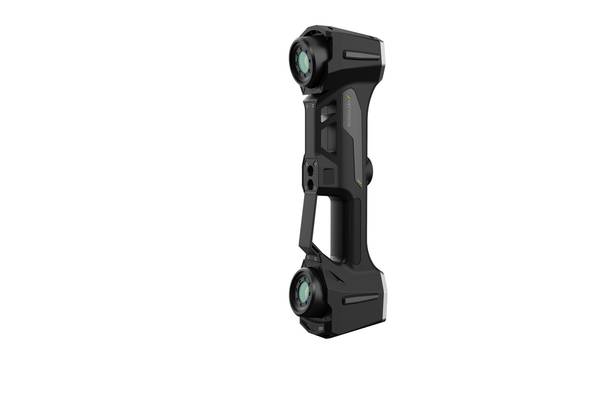
What Are 3D Scanning Reference Points? What Are 3D Scanning Reference Points? 3D scanning reference points — commonly called fiducial markers — are fixed.
What Are 3D Scanning Reference Points?
What Are 3D Scanning Reference Points?
3D scanning reference points — commonly called fiducial markers — are fixed, identifiable coordinate anchors applied to a part or fixture before scanning begins. Their function is straightforward: each marker carries a known spatial position that the scanner software recognizes across multiple views.
When a scanner captures data from different angles or separate scan positions, the software uses these shared points to align and register each dataset into a single coordinate system.
Key Points at a Glance
- 3D scanning reference points — commonly called fiducial markers — are fixed, identifiable coordinate anchors applied to a part or fixture before…
- Reference points serve as fixed spatial anchors that let a 3D scanner register surface geometry inside a stable coordinate frame.
- Reference point selection directly affects scan alignment accuracy, repeatability, and downstream GD&T reporting.
- Reference points serve a specific function in the 3D scanning workflow: they establish a stable coordinate frame when the scanner cannot reliabl…
The core purpose is reducing alignment error during stitching. Without reliable reference geometry, overlapping scan patches drift relative to one another, producing distorted models or failed registrations on large parts, thin edges, or feature-poor surfaces. Reference points also enable repeatable comparison between acquired scan data and nominal CAD geometry for quality verification.
In GD&T workflows, this means first-article inspection, in-process checks, and wear analysis can reference the same datum structure scan after scan.
Common physical formats include adhesive retroreflective dots, magnetic markers for ferrous tooling, and fixture-integrated datum targets.
| Sector | Typical Reference Point Approach | Primary Driver |
|---|---|---|
| Automotive OEM | Adhesive retroreflective dots on body-in-white panels | Alignment across large, low-feature sheet metal surfaces |
| Aerospace MRO | Fixture-integrated datums or temporary magnetic targets | Repeatability for damage mapping and blend-out verification |
| Medical device | Small adhesive markers on implants or instruments | Registration on small, high-tolerance parts with limited free-form geometry |
| Energy infrastructure | Magnetic or clamp-mounted targets on weldments and castings | In-field scanning where adhesive adhesion is unreliable |
The markers themselves are not measurement features. They are temporary or semi-permanent coordinate anchors. Once scanning is complete, the software removes their geometry from the final mesh.
Retroreflective targets are common because the scanner’s structured-light source reflects strongly off their surface, making them detectable even at oblique angles or under mixed shop lighting. For automated or repeat-measurement cells, permanent fixture datums are often preferred over disposable dots because they eliminate per-scan marker placement variability.
A common misconception is that more reference points always improve accuracy. In practice, excessive or poorly distributed markers can introduce local registration conflicts. Effective placement follows a few rules: points should be distributed across the full scan volume, avoid clustered groupings on small areas, and remain visible from multiple scan positions. Feature-rich areas need fewer markers;
blank or smooth areas need more.
Working Principles of 3D Scanning Reference Points
Reference points serve as fixed spatial anchors that let a 3D scanner register surface geometry inside a stable coordinate frame. Without them, feature-poor regions such as large sheet-metal panels or smooth castings drift during scanning and produce warped datasets.
Placement and coordinate frame creation. Adhesive retroreflective dots are applied directly to the part or to the holding fixture. Each dot pattern must form a non-symmetric, unique constellation. The scanner identifies at minimum three visible points in any single frame, and that triplet defines a local rigid-body transform for the captured surface patch.
Optical detection. Blue laser scanners illuminate the dots at high contrast against the part surface. The sensor extracts dot centroids in parallel with the laser line data, so point positions are captured relative to the surface in the same exposure.
Stitching and alignment. Scanning software matches overlapping dot patterns between consecutive frames. Because each dot constellation is geometrically unique, the software computes the rigid transformation that aligns one frame to the next. This alignment chain remains traceable to the physical dots.
| Mounting method | Optimal use case |
|---|---|
| Part-mounted | Single-part inspection, first-article checks, freeform surfaces |
| Fixture-mounted | Repeated measurements, small parts, areas where adhesive residue is unacceptable |
Fixture-mounted points keep the part surface untouched and speed up batch inspection. Part-mounted points travel with the object and work better when the part must be moved between scans. The choice depends on whether the inspection workflow prioritizes surface integrity or setup repeatability.
Key Selection Criteria for 3D Scanning Reference Points
Reference point selection directly affects scan alignment accuracy, repeatability, and downstream GD&T reporting. A marker that drifts, delaminates, or lacks proper contrast will introduce error before the scanner ever captures surface data. Engineers should evaluate markers against the specific sensing technology in use—laser scanners require different retroreflective properties than structured light systems.
The table below organizes the primary criteria against typical industrial contexts. Use it to narrow options before validating performance on a representative part surface, not as a substitute for on-site testing.
| Criterion | Core Considerations | Typical Application Contexts |
|---|---|---|
| Marker Form Factor | Adhesive vs. magnetic vs. fixture-integrated; retroreflective contrast for laser or structured light sensing | Cleanroom medical device assembly, aerospace composite inspection, automotive body panel scanning |
| Surface Compatibility | Adhesion on textured, curved, low-surface-energy, or delicate substrates; residue-free removal | High-gloss automotive trim, carbon fiber aerospace components, precision medical implants |
| Environmental Resistance | Stability under temperature swings, humidity, dust, or outdoor UV exposure | Wind turbine component inspection, engine test cell measurement, outdoor energy infrastructure surveys |
| Quality Traceability | Calibration documentation, batch traceability, conformance to ISO or ASME audit requirements | First Article Inspection (FAI), AS9100 aerospace audits, ISO 13485 medical device compliance |
| Reusability Profile | Single-use adhesive dots vs. multi-use magnetic or fixture-based targets; cycle durability | High-volume powertrain inspection, low-volume aerospace prototype development |
Prioritization should follow the workflow’s dominant constraint, not a generic checklist. A regulated aerospace FAI program will place quality traceability above reusability because audit documentation carries equal weight to measurement data.
A high-volume automotive line scanning hundreds of parts per shift will prioritize marker durability and quick replacement cycles, since downtime from failed adhesion costs more than marker expense. High-gloss or low-surface-energy substrates often force surface compatibility to the top of the list regardless of other preferences—if the marker will not stay put, nothing else matters.
A practical validation step: run a repeatability test on the actual production surface before committing to a marker type. Scan the same marked part five times without moving the markers, then again after removing and reapplying them. The first test isolates scanner noise; the second exposes marker placement variability. This data, not supplier claims, should drive the final decision.
Use Boundaries of 3D Scanning Reference Points
Use Boundaries of 3D Scanning Reference Points
Reference points serve a specific function in the 3D scanning workflow: they establish a stable coordinate frame when the scanner cannot reliably lock onto part geometry alone. This occurs most often with large, continuous surfaces, symmetrical castings, or components with repeated features that lack unique identifiers.
In these cases, a distributed field of reference points gives the alignment algorithm fixed anchors across multiple scan passes, preventing drift and maintaining stitch integrity.
The strongest fit for reference-point-based alignment falls into four industrial scenarios. First, workflows requiring high alignment accuracy across the full scan volume. Second, complex part geometries with deep pockets, hidden features, or limited line-of-sight that force the scanner to reposition frequently.
Third, large assemblies scanned from multiple angles where the accumulated frame-to-frame error would otherwise exceed tolerance. Fourth, repeatable inspection cycles in quality control, where the same reference point layout must be reproduced across serial production batches.
The table below summarizes the alignment approach best matched to typical industrial conditions.
| Workflow Condition | Primary Alignment Method | Complementary Method | Typical Application Context |
|---|---|---|---|
| Continuous feature-rich surfaces | Feature-based alignment | Reference points for redundancy | Machined castings, billet parts with datums |
| Large, uniform or symmetrical surfaces | Reference-point-based alignment | Feature targets at machined datums | Sheet metal, composites, weldments |
| Deep cavities and hidden features | Reference points around access zones | Single-laser line scanning for hole interiors | Transmission housings, manifold internals |
| Repeatable serial inspection | Fixed reference point layout | Fixture-based datum simulation | First-article inspection, PPAP, in-process checks |
For parts with distinct, stable geometric features — machined datums, drilled holes, sharp edges, or unique surface patterns — feature-based alignment often delivers equal or better results with less setup time. In practice, many metrology groups run both methods concurrently.
Reference points provide a fallback when the scanner loses feature lock, while the machined features confirm that the reference point frame has not shifted relative to the part datums. This redundancy is not overkill; it is cheap insurance for traceable measurement data.
The fit with lean manufacturing and Industry 4.0 initiatives is direct. Reference points create a repeatable, documented scan setup that can be reproduced by different operators on different shifts with minimal variation. When scan data flows into a digital twin or quality management system, the alignment method becomes part of the measurement record.
That traceability matters when an auditor asks how the scan was registered, or when a supplier disputes a dimensional nonconformance. A stable, documented reference point layout answers those questions without ambiguity.
Specialized cases do exist where reference points add little value. Automated in-line scanning cells with fixed sensor positions and part fixtures often rely on the fixture itself as the coordinate reference. Parts with dense, unique texture — as-cast surfaces with consistent roughness patterns, for example — may align reliably through feature matching alone.
Photogrammetry-assisted scanning of very large objects may use coded targets measured by a separate camera system before the handheld scanner takes over. These are not limitations of reference points; they are cases where a different alignment tool fits the application more cleanly.
The engineering judgment lies in choosing the method that minimizes setup effort while meeting the required measurement uncertainty for the feature tolerances in play.
Common Misconceptions About 3D Scanning Reference Points
Reference points serve as fixed, identifiable anchors that allow a 3D scanner to align multiple frames into a single coordinate system. Despite their widespread use in dimensional inspection and reverse engineering, several persistent myths still lead to poor workflow decisions on the shop floor.
Misconception 1: Adding more reference points always improves scan accuracy. This is one of the most common assumptions, and it is generally incorrect. Accuracy depends less on the total count and more on distribution, stability, and line-of-sight across individual scan frames.
Engineers familiar with GD&T datum reference frame best practices understand that a small number of well-placed, visible points can outperform a dense field of poorly positioned ones. Over-populating a surface may actually introduce noise or interfere with feature extraction, especially on parts where surface data matters more than alignment data.
The principle is simple: place points where they can be seen consistently, not everywhere.
Misconception 2: All reference points are compatible with every 3D scanner. Marker detectability varies with the scanner’s sensing technology, field of view, and optical resolution. A point that works well with a blue laser scanner may be invisible to a structured light system, and vice versa. Teams should verify compatibility between the marker type and the scanning hardware before starting a project.
Misconception 3: Reference points are only necessary for large parts. In fact, small, high-precision components benefit just as much. Medical implants, aerospace fasteners, and similar parts often require repeatable, high-accuracy inspection cycles. Reference points help maintain alignment stability across multiple scans, even when the part itself is only a few millimeters in size.
| Factor | Impact on Scan Accuracy |
|---|---|
| Point distribution | High — affects alignment stability across frames |
| Point visibility | High — must remain detectable from multiple angles |
| Total point count | Moderate — more points do not automatically improve results |
| Hardware compatibility | Critical — marker type must match scanner technology |
| Part size | Low — small parts need reference points as much as large ones |
INSVISION scanning systems are designed with these principles in mind, supporting workflows where reference point placement follows measurement requirements rather than arbitrary quantity targets.
Related Concepts in Industrial 3D Scanning Alignment
Fiducial calibration validates the positional accuracy of 3D scanning reference points against a traceable standard. Without this step, repeatability claims mean little.
Scan stitching combines overlapping datasets into one mesh. Each scan must share at least three common reference points with the previous scan. Misalignment here propagates as cumulative error across large surfaces like automotive body panels.
Datum reference frames bridge GD&T callouts on drawings and digital scan data. Reference points placed on datum features—planes, holes, bosses—translate the part coordinate system into the scanner’s software, making deviations from nominal directly comparable to CMM output.
CMM alignment follows the same logic. A CMM probes datums to establish the part frame; a scanner uses reference points. Cross-system consistency depends on both workflows referencing identical datum features, especially in aerospace MRO where legacy CMM programs and new scan data must agree.
Digital twin data correlation extends this traceability to lifecycle models. Automotive OEMs feeding scanned as-built geometry into digital twins need reference point metadata to align subsequent scans over time, supporting wear analysis and design validation.
| Concept | Role of Reference Points | Typical Application |
|---|---|---|
| Fiducial calibration | Validates coordinate accuracy | ISO 17025 traceability |
| Scan stitching | Common alignment targets | Large surface digitization |
| Datum reference frames | Links GD&T to scan data | First-article inspection |
| CMM alignment | Cross-system datum consistency | Aerospace MRO |
| Digital twin correlation | Longitudinal model updates | Predictive maintenance |
INSVISION systems support these workflows through standard reference point compatibility, though the principles apply regardless of hardware.
3D Scanning Reference Points and INSVISION Solutions
Reference points in industrial 3D scanning are physical or projected markers placed on or around a part. Scanners detect these markers to establish a coordinate frame and stitch overlapping scans into a single dataset. Without them, scan alignment can drift, particularly on large surfaces, smooth geometries, or parts with repetitive features. Reference points reduce that uncertainty.
INSVISION scanning hardware is engineered to detect reference points across multiple scanning modes. This means the same reference point set can support switching between precision scanning, high-speed scanning, and deep-hole scanning without re-marking the part. That capability matters in workflows where a single inspection sequence must cover both fine feature detail and broader surface geometry.
| Scanning context | Reference point role | Typical application |
|---|---|---|
| Small precision components | Dense marker placement for local alignment | Turbine blade inspection, medical device housings |
| Large assemblies | Sparse marker network for global registration | Automotive body-in-white, aerospace tooling |
| Deep holes or recesses | Markers on surrounding surfaces only | Casting inspection, machined pockets |
The hardware supports standard industrial reference point types, including adhesive dot markers and magnetic targets. Compatibility with conventional marker sizes and reflectivity levels allows INSVISION systems to integrate into existing inspection workflows without proprietary consumables. For quality engineers, this simplifies setup validation.
For procurement, it avoids locking a measurement program into a single marker supplier. The practical result is consistent scan registration across part sizes ranging from small machined components to large fabricated assemblies.
Frequently Asked Questions About 3D Scanning Reference Points
Reference points—often called targets, markers, or fiducials—anchor scan data to a stable coordinate system. Without them, point-cloud alignment drifts, especially on large or featureless surfaces. The answers below address the practical concerns raised most often by engineers and quality teams.
#### Can 3D scanning reference points be reused across multiple inspection cycles?
Reusability depends entirely on marker design.
| Marker Type | Typical Use Cycle | Key Considerations |
|---|---|---|
| Adhesive markers | Single-use | Prone to contamination; adhesive degrades after removal. Not recommended for cleanroom environments. |
| Magnetic markers | Reusable | Engineered for repeated attachment on ferromagnetic surfaces. |
| Fixture-integrated targets | Reusable | Built into holding fixtures; ideal for high-volume, repeat-part inspection. |
Adhesive markers are cheap and fast, but they are consumables. In a cleanroom or any environment where cross-contamination is a documented risk, single-use adhesive markers are the standard choice. Magnetic and fixture-based targets cost more upfront, yet they remove recurring material cost and reduce setup variation between cycles.
#### Will reference points damage the surface of high-value parts?
Not when applied and removed according to manufacturer instructions.
Non-damaging adhesives for industrial metrology are formulated to release cleanly from metals, engineering polymers, and most coated surfaces. Magnetic markers use padded or coated contacts to prevent scratching. That said, “most” is not “all.” Polished medical implants, thin-film coatings, and bare composite layups deserve a material compatibility check before full application.
A small test patch on a non-critical area is standard practice. If residue or surface change appears, switch to a fixture-based targeting approach.
#### How do reference points support compliance with industrial quality standards?
Reference points create the traceable, repeatable coordinate frame that makes scan data defensible in an audit.
Standards like ISO 10360 define how coordinate measuring systems are verified for accuracy. Reference targets matter because they establish the alignment between the physical part and the digital model. Without stable, documented reference geometry, repeatability suffers—and repeatability is exactly what an auditor reviews. Sector-specific requirements add another layer.
AS9100 (aerospace) and ISO 13485 (medical devices) both expect documented measurement processes with controlled inputs. A defined reference point strategy—type, placement, and removal procedure—becomes part of that controlled process. For first-article inspection or GD&T callouts, the quality record should note how the part was fixtured and targeted. That record is what turns a good scan into a passable inspection report.
Metrology teams that treat reference points as an afterthought usually pay for it in rework or disputed results. Treating them as part of the measurement plan—specified, documented, and verified—keeps the data defensible.
Summary of 3D Scanning Reference Point Fundamentals
3D scanning reference points are coordinate anchors placed on or around a workpiece. Their primary role is to give the scanner a stable, repeatable frame of reference during data capture. Without these anchors, scan software struggles to align overlapping patches, especially on parts with large, featureless, or highly reflective surfaces. The points are not merely accessories;
they directly influence registration accuracy and the integrity of the final mesh.
Selection is driven by application fit rather than a single “best” option. Three factors matter most: surface adhesion, optical contrast, and dimensional stability. Adhesive-backed targets work well on rigid metal or composite parts. Magnetic targets suit ferrous surfaces where adhesive residue is unacceptable.
For high-precision work, calibrated targets with tight diameter tolerances reduce scaling errors during photogrammetry-assisted alignment.
| Criterion | Practical Consideration | Typical Application Fit |
|---|---|---|
| Adhesion type | Adhesive vs. magnetic vs. reusable | Oily surfaces, clean room, MRO tear-down |
| Target diameter | Smaller for fine detail, larger for wide-area tracking | Small castings vs. automotive body panels |
| Pattern contrast | Matte white/black for blue laser visibility | Polished or dark-coated metals |
| Stability | Low thermal expansion; no lifting during scan | Long scan sessions, temperature-shifted floors |
The function of reference points extends beyond alignment. They support traceability in first-article inspection and reverse engineering workflows. When a scan is repeated weeks later—or by a different technician—the same reference layout allows comparable results. This matters for ASME Y14.5 verification and digital twin updates, where point-cloud drift is not acceptable.
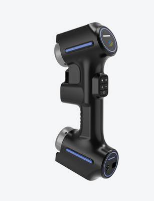
A neutral, practical note: matching the reference point type to the scanning workflow and hardware avoids most alignment failures. No single target format solves every problem. The right choice is the one that stays fixed, remains visible to the sensor, and does not alter part geometry.
Paired with compatible scanning technology, consistent reference point practice yields repeatable data across inspection, reverse engineering, and digital manufacturing use cases. INSVISION systems are designed to work with standard reference point schemes, but the fundamentals above apply across platforms.
- What Is 3D Scanning? Principles, Workflow, and Industrial Applications 3D scanning is a digital measurement technology that converts the surface geometry of physical objects into 3D data. This entry covers its working principles, core parameters, industrial use cases, common misconceptions, and related technical…
- What Is a 3D Scanner? Types, Parameters, and Selection Criteria A 3D scanner captures three-dimensional surface data from physical objects and converts geometry, dimensions, and features into digital data for inspection, reverse engineering, and modeling.
- What Is 3D Scanning Accuracy? Accuracy, Repeatability, and Resolution Explained 3D scanning accuracy describes how closely scan data matches an object's actual geometry and dimensions. It is assessed through local accuracy, volumetric accuracy, stitching accuracy, repeatability, and resolution.
- What Is Point Cloud Data? Point Clouds, Meshes, and CAD Models in 3D Scanning Point cloud data is an important raw data format in 3D scanning. It consists of discrete 3D coordinate points that describe object surface geometry and support inspection, reverse engineering, modeling, and archiving.
Hangzhou Insvision Technology Co., Ltd.
Address: Building 1, No. 1399 Liangmu Road, Yuhang District, Hangzhou, Zhejiang 311121, China
Copyright © Hangzhou Insvision Technology Co., Ltd. All rights reserved.
Copyright © Hangzhou Insvision Technology Co., Ltd. All rights reserved.