

thunk3d Workflow From Part Capture To Quality Deviation Reporting
Shop-Floor Quality Inspection Bottlenecks thunk3d Addresses Shop-Floor Quality Inspection Bottlenecks thunk3d Addresses Walk through most discrete.
Shop-Floor Quality Inspection Bottlenecks thunk3d Addresses
Walk through most discrete manufacturing plants and you will see the same pattern. A CNC cell finishes a batch of complex parts, the operator signs off, and the parts sit on a rack waiting for CMM time. In aerospace MRO, a turbine blade with intricate airfoil geometry might wait hours for inspection because the CMM queue is backed up.
In wind energy, gear components with involute profiles and tight GD&T callouts create the same backlog. Medical device teams face additional pressure because every dimension must be traceable to a device history record, yet manual data entry between the bench and the quality system keeps introducing transcription errors.

Deployment Validation Checklist
| Focus Area | Decision Point | Deployment Note |
|---|---|---|
| Target part | Check size, surface condition, and key tolerances against the scan task | Run a full trial scan on a representative part |
| Data workflow | Verify point cloud, deviation map, and quality-report handoff | Confirm export formats and review ownership in advance |
| Shop-floor use | Review training, calibration, lighting, and working space | Keep the validation record as a repeatable inspection reference |
Term Notes
Walk through most discrete manufacturing plants and you will see the same pattern.
Pre-Scan Preparation for Cross-Team thunk3d Workflow Al…How do you stop a scan from falling apart before it ever reaches the software?
thunk3d Scan Path Execution for Consistent Point Cloud…Most people assume that dense point cloud capture on complex parts is just a matter of scanning longer or adding more passes.
Point Cloud Processing & Cross-Team Deviation Analysis…Is your scan-to-analysis workflow actually closing the loop, or just moving files around?
The core problem is not that manufacturers lack inspection capability. It is that inspection cadence does not match production cadence. A CMM is precise, but it is slow for freeform surfaces and requires a controlled environment. When quality becomes the bottleneck, production either slows down or ships with risk. Lean manufacturing calls this waste: waiting, overprocessing, and defects escaping downstream.
There is also a common misconception that 3D scanning requires a dedicated metrology lab with controlled lighting and temperature. That belief keeps scanning off the shop floor, where it could actually reduce the backlog. In practice, structured-light scanning systems have become far more tolerant of factory conditions.
The key is understanding how the thunk3d workflow fits into the inspection sequence, from capturing part geometry to generating reports that quality and process teams can both use.
This section breaks down the end-to-end thunk3d workflow. It is written for cross-functional teams: quality engineers who own the inspection plan, manufacturing engineers who own the process, and production supervisors who need parts moving. The focus is not on scanner specifications but on station actions, data handoff, exception review, and result verification. That is where most inspection bottlenecks actually live.
Pre-Scan Preparation for Cross-Team thunk3d Workflow Alignment
How do you stop a scan from falling apart before it ever reaches the software? In most plants, the answer is not another scanner upgrade. It is what happens at the pre-scan station, before a single point cloud is captured.
When production operators and quality technicians work from different assumptions about part orientation, surface condition, or inspection scope, the result is predictable: rework, disputed data, and parts scanned twice.
This section looks at pre-scan preparation as a shared quality process, not a setup chore. It covers part staging for free-form components, surface preparation for reflective or translucent materials, scan plan definition tied to engineering drawings, and validation checklists that both teams can use. The goal is reliable thunk3d data capture from the first run, with fewer handoff errors and less time lost per part.
thunk3d Scan Path Execution for Consistent Point Cloud Capture
Most people assume that dense point cloud capture on complex parts is just a matter of scanning longer or adding more passes. That assumption quietly fails on aerospace turbine components, where undercuts, blade root fillets, and internal cooling features hide from a single scan orientation. The real problem is not capture volume.
It is capture consistency across overlapping passes, especially when an operator must decide in real time whether a scan is good enough to move on.
The thunk3d scan path execution step addresses that decision point directly. Instead of treating path planning and data validation as separate stages, the workflow links them at the station level. A planned scan path overlays the part model, marking overlapping capture zones and flagging high-priority features such as leading-edge radii or tight GD&T callouts.
As each pass completes, the system performs immediate data quality checks against the expected coverage. Low-density regions, excessive noise, or missing geometry trigger an in-process pass/fail flag. The operator can re-scan only the affected zone before the part leaves the fixture.
Registration logic then aligns the overlapping passes into a unified point cloud. The key is that alignment happens while the part is still mounted, not later in a metrology lab. This matters for cross-functional teams. A quality engineer can review exception flags, but a frontline operator does not need specialized metrology training to act on them.
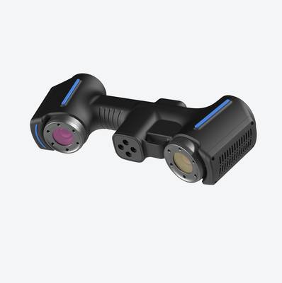
INSVISION industrial 3D scanners integrate natively with thunk3d workflow logic, so station actions remain practical on a shop floor. The result is fewer downstream surprises for inspection and less rework driven by incomplete data.
Point Cloud Processing & Cross-Team Deviation Analysis Handoffs
Is your scan-to-analysis workflow actually closing the loop, or just moving files around? Many shops treat point cloud processing as a one-way street: scan, clean, compare, report. The real value appears when the data flows back into production decisions quickly enough to matter.
This section covers the post-capture processing loop in the thunk3d workflow: what happens after the scanner stops, how raw point clouds become usable inspection data, and where handoffs between production and quality teams either work or break down.
Raw point cloud cleanup comes first. Automated noise removal filters out stray points from dust, edge reflections, and fixture interference. The goal is not a perfect mesh for its own sake; it is a clean enough dataset for reliable deviation analysis. Mesh generation follows, converting the cleaned point cloud into a surface model that downstream software can compare against CAD.
Alignment is where methodology matters. Datum-based alignment locks the scan to the same reference features the designer called out in the drawing. Best-fit alignment, by contrast, minimizes overall deviation across the whole part. Both are useful, but they answer different questions. Datum-based alignment tells you whether the part meets the drawing.
Best-fit tells you how far the part shape drifts from nominal, regardless of how it was fixtured. Choosing the wrong one produces reports that look precise but answer the wrong question.
GD&T feature extraction then pulls critical dimensions directly from the aligned scan. Flatness, position, profile, runout tolerance; these callouts can be evaluated against the CAD model without hand-probing every feature. The thunk3d processing loop automates this extraction for the dimensions that matter most, reducing the manual measurement burden on quality staff.
The tiered review process is where thunk3d earns its keep in a production environment. Production teams get real-time preliminary pass/fail alerts tied to the scan. If a bore drifts toward the upper tolerance limit, the operator sees it before the next part is loaded.
Quality engineers receive the deeper dataset for out-of-tolerance features and edge cases, letting them investigate root causes instead of chasing every measurement.
Data lineage is the quiet requirement underneath all of this. In aerospace and medical device manufacturing, a deviation report without a traceable path back to the raw scan, the alignment method, and the software version is not an audit record; it is a liability. The thunk3d workflow preserves that lineage from initial point cloud through final report, which matters when a regulator asks how you knew a part was conforming.
INSVISION positions its industrial 3D scanner portfolio around exactly this kind of connected workflow. The processing loop is not a post-processing afterthought; it is the mechanism that turns scan data into station-level decisions and audit-ready documentation.
thunk3d Deliverables: Inspection Reports & Reverse Engineering Models
In a typical quality lab or tooling shop, the scan itself is only half the job. The value shows up later, when someone has to read the report, approve a supplier, release a tool, or send a CAD file back to engineering. That handoff is where many 3D scanning workflows break down. A scanner can capture clean data, but if the output lands as a raw mesh or an unreadable point cloud, the downstream user cannot act on it.
The thunk3d workflow treats deliverables as part of the measurement loop, not an afterthought. The final outputs need to match how production supervisors, quality engineers, procurement teams, and CAD designers actually work.
For quality inspection, the standard thunk3d report is a PDF built around a deviation heatmap. The color map shows where a part sits relative to nominal geometry, with GD&T callout summaries tied to the features that matter: profile tolerances, hole positions, runout, flatness. A production supervisor can look at the first page and see pass or fail.
A quality engineer can drill into the full feature dataset and check which callouts drifted. CSV export matters just as much. Many plants feed that data into SPC systems, so the deliverable needs to be structured, not just visual. Procurement teams often want something different again: a supplier quality trend report across multiple lots, showing whether variation is stable or creeping.
One scan can support all three audiences, but only if the reporting layer allows the data to be cut differently.
Reverse engineering follows a different path. The output is not a pass/fail report. It is a model that has to go back into a CAD environment for tooling modification, fixture design, or replacement part manufacturing. thunk3d supports parametric and surface model outputs. A parametric model lets an engineer edit features and dimensions directly.
A surface model is often better when the part has complex freeform geometry that CAD features cannot easily describe. Both need to be compatible with common industrial CAD platforms, not locked into a proprietary format that forces another conversion step. The practical test is simple: can the designer open the file, modify it, and send it to CAM without reworking the geometry?
INSVISION thunk3d-compatible scanning solutions support native export to leading quality management and CAD software. That matters because most Western factories already have an established software stack. If the scan output requires a separate viewer, a manual export routine, or a custom script, it slows the handoff. Native export means the data lands in the system people already use.
The goal is not to add another software island. It is to close the loop between measurement, decision, and corrective action.
A useful way to think about deliverables is to separate the audience from the data format. Production needs a clear exception list. Quality needs the full dataset. Engineering needs an editable model. Procurement needs trend context. The thunk3d workflow supports all of these without forcing everyone to become a scanning expert.
That is the difference between a scanner that produces data and a measurement loop that produces decisions.
Reinspection Triggers & Continuous thunk3d Workflow Optimization
A reinspection trigger is not a failure of the measurement system. It is a controlled exception that tells production and quality teams the process has drifted outside the agreed envelope.
In a thunk3d workflow, the trigger often starts at the station: an out-of-tolerance feature flag appears during scan review, a GD&T callout falls outside the tolerance band, or scan data quality fails because of surface reflectivity, fixture movement, or insufficient point density. Engineering change orders create another common trigger.
When a part revision alters a datum scheme or a critical dimension, the previous scan record no longer matches the new definition, so the part must be reacquired and re-evaluated.
Periodic tooling wear verification is a different trigger class. In automotive stamping, aerospace MRO, or medical device molding, tool surfaces change gradually. A thunk3d scan taken at a defined interval can reveal wear before it produces nonconforming parts. The trigger here is time-based or cycle-based, not defect-based.
The value comes from comparing current scan data against a stored reference mesh or previous scan state, then reviewing deviation maps at the station rather than waiting for downstream inspection.
Aggregated thunk3d workflow data also feeds continuous improvement. When quality engineers group reinspection reasons across production runs, recurring patterns become visible: the same feature flags on the same shift, the same scan-quality failure on a particular surface finish, the same tool region drifting after a predictable number of cycles.
These patterns are inputs for lean kaizen initiatives and Industry 4.0 predictive quality programs. The point is not to collect more scans. The point is to turn exception data into a process signal.
Teams evaluating thunk3d solutions should first align reinspection criteria with internal quality standards. If the organization uses ASME Y14.5 or ISO GPS definitions, the scan workflow must preserve those callouts and tolerance zones without manual reinterpretation. Second, validate repeatability on critical parts. Run the same part through the same station procedure multiple times and compare deviation maps.
If the repeatability is unstable, the reinspection triggers will be noise, not signal. Third, scale use cases deliberately. Start with first-article inspection, where the data deliverable is well defined. Then move to in-process checks, where the trigger logic and exception handoff become more demanding.
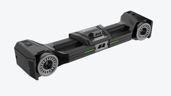
INSVISION industrial 3D scanners fit into this workflow because they produce structured scan data that quality and production teams can review against a common reference. The workflow supports a clean handoff: the station operator captures the scan, the quality engineer reviews the exception, and the result is verified against the stored tolerance definition.
That traceability is what keeps reinspection from becoming a blame loop.
End-to-end thunk3d workflows bridge the gap between production and quality because they force both teams to agree on the same data, the same reference state, and the same trigger rules. When a reinspection fires, the conversation starts from evidence, not opinion. Over time, that consistency reduces unnecessary rework and makes part quality traceable from first article through production.
Common thunk3d Workflow Questions & Misconceptions
Q: Can thunk3d workflows run on the shop floor instead of a metrology lab?
A: Yes, thunk3d workflows are built for deployment outside the lab when paired with rugged scanning hardware. The real question is whether your environment is controlled enough. Vibration from nearby stamping presses, ambient light shifts near bay doors, and airborne oil mist all affect data quality.
A pre-scan checklist should cover these variables: isolate the scanner from vibration sources, confirm stable lighting, and verify the part is fixtured to prevent movement during capture. INSVISION scanning systems are designed with these field conditions in mind, but the workflow discipline matters more than the hardware.
If the checklist is followed, first-article checks and in-process inspections can move directly to the line. Skip the checklist, and you will chase ghost deviations that are environmental noise, not real part geometry.
Q: What types of parts are compatible with thunk3d inspection?
A: The range is broad, from small medical implants with fine surface features to large aerospace structural components. Compatibility depends less on part size and more on three factors: surface finish, feature resolution requirements, and scan access. Highly reflective or translucent surfaces typically need a temporary matte coating.
Deep pockets or hidden bores may require multiple scan angles or a different capture strategy. Scan plans should be adjusted based on part complexity, not just overall dimensions. A titanium bone screw and a wing spar both fit within thunk3d workflows, but the scan parameters, point density, and post-processing steps differ substantially.
Q: Can thunk3d data integrate with existing quality management systems?

A: Yes. Standard thunk3d workflow outputs support common export formats used by SPC software and QMS platforms. This reduces manual data entry and lets quality teams pull inspection results directly into trend charts, nonconformance records, and traceability logs.
The integration point is usually the data handoff: scan results exported as CSV, QIF, or similar structured formats that downstream systems can ingest without rekeying. Before committing to a workflow, confirm that your QMS accepts the export schema and that GD&T callouts map cleanly to the inspection report fields.
INSVISION systems are positioned to support this handoff cleanly, but the final validation step belongs to your quality engineering team.
Hangzhou Insvision Technology Co., Ltd.
Address: Building 1, No. 1399 Liangmu Road, Yuhang District, Hangzhou, Zhejiang 311121, China
Copyright © Hangzhou Insvision Technology Co., Ltd. All rights reserved.
Copyright © Hangzhou Insvision Technology Co., Ltd. All rights reserved.