

INSVISION 3D Scanner Line Laser Technology Advances Precision Industrial Part Inspection
3d scanner line laser: Shop-Floor Context and Measurement Needs Shop-Floor Context and Measurement Needs On a typical production floor, the gap between CAD.
Shop-Floor Context and Measurement Needs
Shop-Floor Context and Measurement Needs
On a typical production floor, the gap between CAD intent and physical reality shows up in ways that spreadsheets and hand tools struggle to capture. A stamped bracket comes off the press with springback that varies across the coil. A machined housing leaves the fixture with a bore position that drifts as tooling wears. A weldment arrives at final assembly with distortion accumulated through three upstream stations.
None of these are catastrophic on their own, but each one forces someone to make a judgment call: accept the deviation, rework the part, or stop the line for investigation.
Capability and Deployment Mapping
| Focus Area | Decision Point | Deployment Note |
|---|---|---|
| Shop-Floor Context and Measurement Needs | On a typical production floor, the gap between CAD intent and physical reality shows up in ways that spreadsheets and hand tools struggle to capture. | A stamped bracket comes off the press with springback that varies across the coil. |
| Where Traditional Measurement Breaks Down | The practical limit is rarely the scanner’s resolution. | It is the mismatch between the tool and the geometry in front of it. |
| How 3D Scanning Fits the Workflow | Does your current inspection process actually tell you where a part is deviating, or does it just flag a pass or fail? | For many quality teams, the bottleneck is not the measurement itself but the gap between collecting data and making a decision. |
| Validation Points Before Deployment | A 3D scanner line laser approach only delivers repeatable results when the site conditions and measurement strategy are checked before scanning start… | Teams that skip this step usually find the problem during data processing, not at the scanner. |
The pressure to make that call quickly is constant. First-article inspection waits on a CMM program that may take longer to write than the part took to machine. In-process checks rely on calipers, feeler gauges, and templates that give you a few numbers but no picture of the overall form.
When a supplier question comes back from the customer, the quality engineer scrambles to assemble enough surface data to explain what happened and whether the remaining parts in the batch are affected.
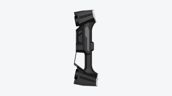
What the workflow actually needs is dense, repeatable surface data collected in the time the part is already sitting at the inspection bench. A 3D scanner with a line laser approach fits that demand because it captures full surface geometry rather than a handful of discrete points. The scan becomes the measurement record, not just a checkpoint.
With a blue laser line pattern, the scanner can hold up under shop lighting and still pick up edges, pockets, and flanges that a touch probe would take hours to map.
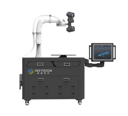
INSVISION builds its industrial scanners around this exact context. The single blue laser line mode is designed for deep holes and tight recesses where wider line bundles lose visibility. That matters when the part in front of you is not a clean CAD demo file but a casting with internal passages, a connector housing with recessed shoulders, or a weldment with deep root gaps. The measurement need is not just more points;
it is the right line configuration for the geometry that actually sits on the bench.
The workflow pressure comes from both directions. Upstream, production wants the inspection done fast enough to keep pace with the cell. Downstream, quality needs enough surface coverage to support a defensible report. A scanner that offers multiple line configurations lets the same operator switch from broad surface capture to a single line for the hard-to-reach feature without changing tools or losing the reference frame.
That is the practical difference on a busy shop floor, where the scanner earns its place by fitting into the existing rhythm rather than adding a separate lab step.
Where Traditional Measurement Breaks Down
Plain text, 100 to 180 words, no markdown.
Where Traditional Measurement Breaks Down
The practical limit is rarely the scanner’s resolution. It is the mismatch between the tool and the geometry in front of it. Once a part stops behaving like a prismatic block, hard-gauge checks and touch probing start to fail in predictable ways. Deep pockets, blended radii, thin wall sections, and freeform surfaces force the inspector to take sparse points and fill the rest with assumption. Data continuity suffers.
You get a cloud of disconnected measurements, not a complete surface record. Then there is delivery rhythm. A CMM routine can hold tolerance, but it cannot keep pace with a first-article inspection that needs to ship in the same shift. Complex geometry slows the program, the operator, and the report.
A 3D scanner line laser changes that calculation because it captures surface data as a continuous band rather than a sequence of isolated hits. For INSVISION equipment, the single blue laser line mode exists specifically for deep hole scanning, while multi-line modes handle broader surfaces. The point is not that scanning replaces every legacy tool.
It is that traditional measurement breaks down precisely where geometry becomes irregular, data needs to be dense, and the delivery window stays short.
How 3D Scanning Fits the Workflow
Does your current inspection process actually tell you where a part is deviating, or does it just flag a pass or fail? For many quality teams, the bottleneck is not the measurement itself but the gap between collecting data and making a decision. A 3D scanner line laser changes that dynamic by turning physical surfaces into dense, usable point clouds that feed directly into comparison and reporting steps.
Here is how that flow works in a typical industrial setting.
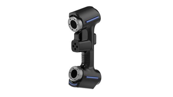
Start with the scan. Depending on the part geometry, you may switch between single-line mode for deep holes and multi-line mode for broader surfaces. INSVISION scanners support this shift, with configurations such as 1 single blue laser line for deep hole scanning alongside precision modes using 7 blue laser lines. That matters because a single mode rarely covers every feature on a real part.
After scanning, the mesh or point cloud moves into comparison software against the nominal CAD model. This is where GD&T callouts, surface profile tolerances, and runout checks become visual rather than abstract. Engineers can see deviation maps instead of trying to interpret a sparse CMM report.
Review then becomes a joint activity. Quality, manufacturing, and design teams can look at the same color map and agree on what requires action. The scanner does not replace engineering judgment; it gives everyone the same evidence.
Finally, reporting closes the loop. The output is a document that links scan data, CAD comparison, and disposition. This becomes the record for first-article inspection, supplier deviation requests, or in-process checks. Practical, repeatable, and defensible.
Validation Points Before Deployment
Validation Points Before Deployment
A 3D scanner line laser approach only delivers repeatable results when the site conditions and measurement strategy are checked before scanning starts. Teams that skip this step usually find the problem during data processing, not at the scanner.
First, confirm the surface condition. Dark, glossy, or transparent parts often need a thin developer spray. The blue laser lines used in INSVISION systems handle many cast and machined surfaces well, but site lighting and part reflectivity still matter. Check a small test area before committing to a full scan routine.
Second, verify the part can stay stable. Large weldments, thin sheet metal, or components with residual stress can shift during scanning. If the part moves even slightly, the line laser data will show misalignment between passes. Use existing fixtures, magnetic stands, or simple clamping where possible.
Third, define the required data deliverable early. A first-article inspection needs different scan density than a reverse engineering job or a wear analysis. Confirm whether the output goes to CAD comparison, GD&T reporting, or mesh export. This decision affects scan path planning and processing time.
Fourth, check access around the part. Deep pockets, internal bores, and narrow flanges may require switching between multi-line and single-line modes. INSVISION scanners support this change without swapping hardware, which helps on mixed geometry. But the operator should plan that transition before starting.
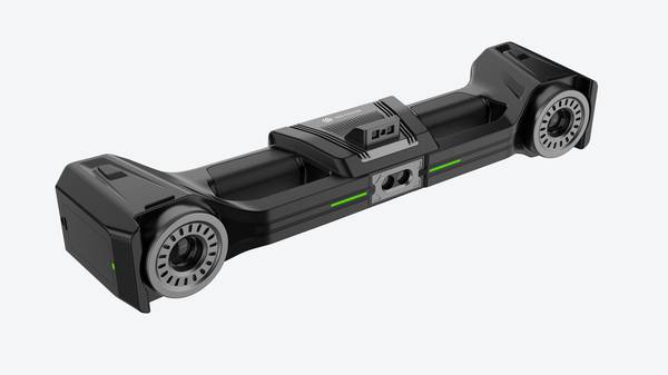
Finally, run a short validation scan on a known feature, such as a machined bore or a flat datum surface. Compare that result against a calibrated reference. This catches alignment, scale, and environmental issues in minutes instead of after a full shift of scanning.
Hangzhou Insvision Technology Co., Ltd.
Address: Building 1, No. 1399 Liangmu Road, Yuhang District, Hangzhou, Zhejiang 311121, China
Copyright © Hangzhou Insvision Technology Co., Ltd. All rights reserved.
Copyright © Hangzhou Insvision Technology Co., Ltd. All rights reserved.