

How Can Truescan3d Resolve High-Tolerance Turbine Blade Inspection Gaps?
truescan3d: High-Tolerance Turbine Blade Inspection: Core Task and Site Constraints High-Tolerance Turbine Blade Inspection: Core Task and Site Constraints.
High-Tolerance Turbine Blade Inspection: Core Task and Site Constraints
Aerospace OEM and MRO quality teams working under AS9100 face a recurring bind. Turbine blades demand full-field geometric verification, but the part itself fights every conventional measurement approach. Curved airfoils, tight-radius cooling holes, and fir-tree root profiles create a surface geometry that contact probing can only sample sparsely.
Reflective nickel-based superalloys and thermal barrier coatings scatter signals unpredictably. Micron-level GD&T callouts leave little room for approximation.
Deployment Validation Checklist
| Focus Area | Decision Point | Deployment Note |
|---|---|---|
| Target part | Check size, surface condition, and key tolerances against the scan task | Run a full trial scan on a representative part |
| Data workflow | Verify point cloud, deviation map, and quality-report handoff | Confirm export formats and review ownership in advance |
| Shop-floor use | Review training, calibration, lighting, and working space | Keep the validation record as a repeatable inspection reference |
Scenario Snapshot
A practical way to read the article is through this scenario:
- High-Tolerance Turbine Blade Inspection: Core Task…: Aerospace OEM and MRO quality teams working under AS9100 face a recurring bind.
- Capture Risks That Compromise 3D Scanning Data for…: Why do so many 3D scanning programs fall apart on superalloy turbine blades before a single usable dataset reaches…
- How Truescan3d Diagnostics Align INSVISION 3D Scann…: A pre-project assessment often reveals more about a scanning task than the scan itself.
The site makes it harder. MRO bays carry shop floor vibration from adjacent machining and engine teardown. Fixture access for in-situ checks is often limited by blade orientation and surrounding hardware. Takt time pressures tied to scheduled engine turnarounds push inspection windows down to hours, not days.
Traditional contact CMM methods struggle here. They deliver point data slowly, miss root-to-airfoil transitions, and require rigid staging that the floor cannot always provide. The truescan3d approach maps these constraints directly: capture geometry under real site conditions, align scan data to nominal models, rescan areas with poor coverage, and validate against tolerance bands before release.
That workflow matters because turbine blade inspection is not just a measurement task. It is a throughput task with flight-safety stakes attached.
Capture Risks That Compromise 3D Scanning Data for Superalloy Turbine Blades
Why do so many 3D scanning programs fall apart on superalloy turbine blades before a single usable dataset reaches the CMM comparison stage? Having spent time on the service side of these deployments, I can tell you the answer rarely sits in the scanner’s rated accuracy. It sits in the interaction between the blade’s physical surface and the measurement strategy applied on-site.
A polished nickel-based airfoil, a curved platform with no flat datums, and an MRO cell running against a takt clock will expose setup weaknesses faster than any lab demo. The truescan3d framework exists because these failures are predictable, and predictability means they can be assessed before scanning begins.
The first risk is surface reflection. Polished superalloy blades behave like mirrors under structured light. The scanner projects a pattern, the surface throws it back unevenly, and the point cloud picks up noise or drops data entirely. Teams often compensate by coating the blade with developer spray, but that introduces thickness variation that can exceed the tolerance band on a leading-edge profile.
A pre-scan diagnostic assessment under the truescan3d approach identifies which zones will return clean data, which will need controlled exposure changes, and whether the blade should be scanned in multiple orientations to reduce specular loss.
The second risk is alignment drift. Turbine blades lack the flat reference surfaces that make registration straightforward on prismatic parts. An airfoil is a continuous curve, and curve-to-curve alignment can drift over a long scan sequence, especially when the operator relies on a turntable and automatic registration.
Without stable reference geometry or coded targets placed in a repeatable pattern, the root and shroud sections may align acceptably while the mid-span profile shifts by a few hundredths of a millimeter. That shift may not be visible in the raw point cloud, but it shows up later as false profile deviation in the inspection report.
A diagnostic pass under truescan3d evaluates whether the blade’s existing features can anchor alignment or whether a fixture-based reference strategy is required.
The third risk is line-of-sight gaps, particularly around internal cooling hole edges. Film cooling holes on the pressure side and leading edge are small, deep, and often angled. A single scan position will capture the surface opening but not the edge break or the immediate subsurface contour. If the inspection deliverable includes hole diameter, position, and edge condition, those gaps become rework triggers.
The truescan3d diagnostic step maps which holes are visible from which scan angles and determines whether additional tilt positions or a different scanner orientation are needed before the main scan begins.
The fourth risk is scan time overrun. MRO takt windows are unforgiving. A blade set that takes three hours to scan instead of ninety minutes does not just delay that work order; it cascades into downstream inspection, blending, and coating operations. Time overrun usually comes from rescanning. The first scan misses data, the operator tries to patch it, alignment shifts, and the whole loop repeats.
A pre-scan diagnostic assessment under truescan3d reduces that loop by identifying the failure points before they consume production time.
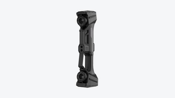
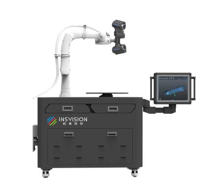
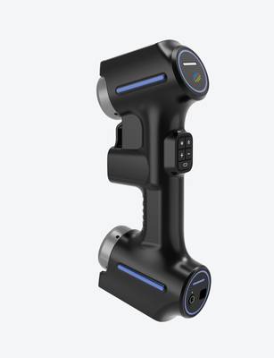
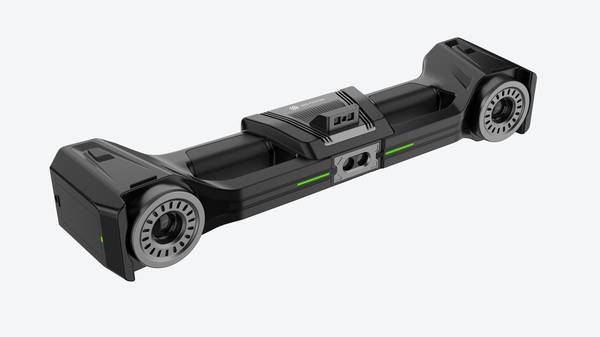
For teams evaluating INSVISION industrial 3D scanners on this type of application, the value is not simply in the hardware. It is in the workflow discipline that the truescan3d framework brings to the capture, alignment, rescan, and validation sequence. The scanner still has to perform, but performance without a pre-scan diagnostic is just a faster way to generate bad data.
On high-tolerance superalloy blades, bad data is expensive. A diagnostic assessment that takes thirty minutes up front can prevent a full shift of rework later. That is the operational logic behind truescan3d, and it applies directly to the constraints outlined in the first section of this series.
How Truescan3d Diagnostics Align INSVISION 3D Scanning Capabilities to Task Needs
A pre-project assessment often reveals more about a scanning task than the scan itself. Without a structured diagnostic pass, engineers tend to compensate with unnecessary scan density, excessive prep, or repeated field visits. The truescan3d workflow changes that sequence. It treats the first site walkthrough as an engineering exercise, not a sales call.
The process starts with constraint mapping. Geometry, material finish, tolerance band, site access, and takt time are cross-referenced before any hardware leaves the case. A turbine blade with fir-tree roots and laser-drilled cooling holes presents different line-of-sight risks than a cast bracket with GD&T callouts. The truescan3d framework forces those risks onto one page.
Hardware and software configuration tuning follows. Scan resolution, light source intensity, and capture speed are adjusted to match surface properties and tolerance needs. A dark, machined root section may require different exposure settings than a bright, as-cast flank. INSVISION scanning solutions are configured through this framework to deliver task-aligned performance, rather than relying on a one-size-fits-all setup.
Scan path planning then eliminates line-of-sight gaps. Cooling holes and fir-tree roots are mapped for approach angle, standoff distance, and overlap. The goal is full coverage without redundant passes that inflate file size and processing time.
Alignment strategy design uses existing part features where possible. Datum surfaces, tooling holes, or machined pads reduce prep time and improve repeatability. This is where the truescan3d diagnostic proves its value: fewer targets, faster setup, and a scan that matches the inspection requirement instead of exceeding it without reason.
Audit-Ready Validation Checklist for Truescan3d Turbine Blade Inspection Data
Most quality managers assume scanner accuracy is the weak link in a turbine blade inspection program. In practice, it rarely is. The real failure point is unvalidated data—point clouds that pass visual review but collapse under audit scrutiny because nobody can prove the scanner was performing correctly at the moment of capture.
That is why INSVISION builds validation into the truescan3d workflow rather than treating it as a post-scan formality. The sequence starts before the blade ever enters the fixture. A reference artifact with certified dimensions is scanned under the same environmental conditions as the production part. If the artifact results drift outside the accepted band, the session stops. No exceptions.
From there, the checklist moves through point density checks on GD&T-critical features—airfoil profile sections, cooling hole diameters, root tooth spacing—then cross-alignment verification across multiple scan positions to catch drift. Deviation maps against nominal CAD close the loop, with tolerance bands documented per feature.
Every deliverable carries the scan parameters, artifact results, alignment residuals, and operator identification needed for ISO 10360 and ASME V traceability.
Predefined rescan triggers matter here. A cooling hole with marginal density triggers a localized rescan, not a full blade rework. That keeps throughput intact without letting borderline data slip downstream. For aerospace and medical device teams, that distinction is what separates a defensible inspection record from an expensive rework event.
Appropriate Use Cases and Scaling Guidance for the Truescan3d Framework
Are you evaluating 3D scanning for parts where the tolerance band is tighter than your current CMM coverage, but the surface geometry makes tactile probing slow or unreliable? The truescan3d diagnostic approach pairs well with INSVISION industrial 3D scanning solutions when the inspection task starts from a constraint, not from a generic “scan everything” impulse.
This framework is best suited for aerospace structural component inspection, medical implant precision metrology, automotive powertrain gear and housing quality control, and energy component MRO such as wind turbine gears or hydroelectric turbine parts.
These sectors share a common thread: freeform surfaces, dense GD&T callouts, and a need for repeatable digital records that support first-article inspection or repair scope decisions.
A practical initial assessment takes three steps. First, define core inspection tasks and tolerance bands. Second, document site and material constraints, including surface finish, access, and part handling. Third, map required data deliverables and turnaround times, such as color maps, mesh exports, or alignment to CAD.
For process and quality engineers evaluating high-tolerance parts, the truescan3d constraint-first approach keeps the scan plan tied to what the part actually requires. That is where the operational value shows up.
Hangzhou Insvision Technology Co., Ltd.
Address: Building 1, No. 1399 Liangmu Road, Yuhang District, Hangzhou, Zhejiang 311121, China
Copyright © Hangzhou Insvision Technology Co., Ltd. All rights reserved.
Copyright © Hangzhou Insvision Technology Co., Ltd. All rights reserved.