

Alat Scan 3D Implementation Checks to Avoid Workflow Gaps
alat scan 3d: Common Alat Scan 3D Deployment Risks in Industrial Quality Workflows The core problem with most failed industrial 3D scanning deployments is.
Common Alat Scan 3D Deployment Risks in Industrial Quality Workflows
The core problem with most failed industrial 3D scanning deployments is rarely the scanner itself. It is the gap between the raw point cloud and the quality document, the inspection sign-off, or the reverse-engineered CAD model that actually moves through the production system. Western manufacturers do not buy alat scan 3D hardware in a vacuum.
They buy a data source that must feed PPAP submissions, MRO teardown records, or incoming inspection logs. When that data does not fit the existing workflow, the equipment ends up under a dust cover.
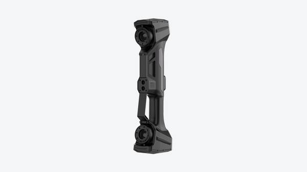
Deployment Validation Checklist
| Focus Area | Decision Point | Deployment Note |
|---|---|---|
| Target part | Check size, surface condition, and key tolerances against the scan task | Run a full trial scan on a representative part |
| Data workflow | Verify point cloud, deviation map, and quality-report handoff | Confirm export formats and review ownership in advance |
| Shop-floor use | Review training, calibration, lighting, and working space | Keep the validation record as a repeatable inspection reference |
Scenario Snapshot
A practical way to read the article is through this scenario:
- Common Alat Scan 3D Deployment Risks in Industrial…: The core problem with most failed industrial 3D scanning deployments is rarely the scanner itself.
- Sample Validation: The First Check for Alat Scan 3D…: Most teams assume a scanner either “works” or “doesn’t.” That’s the wrong frame.
- Integrating Alat Scan 3D Into Existing Quality and…: Walk into most production engineering offices and you will find the same problem: measurement data lives in too ma…
Automotive PPAP is a clear example. A supplier can scan a stamped bracket and generate a dense mesh, but if the software cannot map that mesh to ballooned drawing callouts and export a clean dimensional report, the scanner has not saved time. It has added a parallel process. Quality engineers still return to CMM or hand tools because those outputs match what the OEM actually requires. The failure is not scan accuracy.
It is report compliance.
Aerospace MRO reverse engineering shows the same pattern from a different angle. A turbine component arrives with wear, corrosion, or a missing original print. The shop needs a usable CAD model quickly. A high-resolution scan is only part of the job. The point cloud must be cleaned, aligned, surfaced, and handed to CAM or a repair work order.
If the scan team cannot produce a watertight model within the turnaround window, the scanner becomes a bottleneck rather than a time saver. Delayed cycles in MRO are measured in grounded aircraft hours. That pressure exposes workflow misalignment fast.
Medical device incoming quality has its own bottleneck. Receiving inspection often handles high part mix, small lot sizes, and strict documentation. A scanner that requires extensive setup per part or produces data that cannot integrate with the ERP or quality management system will slow the dock-to-stock process.
The value of alat scan 3D in this setting depends on repeatable fixtures, quick part changeover, and traceable digital records. Without those, the scanner is just another island of data.
These risks are avoidable. They stem from pre-purchase decisions made without mapping the full data path from scan to decision. Structured checks help: define the required report format before selecting software, test scan-to-CAD time on a real worn part, confirm IT compatibility for data storage and MES integration, and involve the quality engineer who will own the output.
Hardware specifications matter, but only after the workflow question is answered. The rest of this article outlines those checks in detail.
Sample Validation: The First Check for Alat Scan 3D Fit
Most teams assume a scanner either “works” or “doesn’t.” That’s the wrong frame. Fit is task-specific. A system that captures a sand-cast pump housing beautifully can struggle on a polished turbine blade or a matte medical device housing with fine texture. The only way to know whether an alat scan 3D solution will hold your tolerance bands is to run your parts through a structured sample validation. Nothing else substitutes.
INSVISION treats sample validation as an engineering checkpoint, not a demo. The goal is to verify three things before any purchase decision: measurement repeatability on your geometry, surface capture performance under your finish conditions, and agreement with your existing CMM baseline. For the validation to mean anything, the samples must be production-grade parts, not idealized CAD prints or clean plastic blocks.
Send parts with full GD&T callouts per ISO or ASME standards. Include the actual surface states that cause trouble in scanning: reflective turbine components from energy applications, bead-blasted or textured housings, dark anodized surfaces, thin edges.
Also provide CMM data for the same features. Without a reference dataset, validation output is just a pretty mesh. With CMM numbers, INSVISION can compare point deviations against your tolerance zones and show whether the scan data agrees where it matters. That comparison often reveals more than the scanner itself: datum alignment choices, feature extraction settings, and mesh processing parameters all affect reported values.
A good validation isolates those variables.
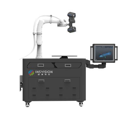
INSVISION’s structured sample validation engagements are built for this. The process checks repeatability across multiple setups, confirms that difficult surfaces are captured without excessive noise or dropout, and verifies that results align with required tolerance bands before you commit to a full solution. It’s the difference between buying on a specification sheet and buying on evidence from your own floor.
Integrating Alat Scan 3D Into Existing Quality and MES Workflows
Walk into most production engineering offices and you will find the same problem: measurement data lives in too many places. CMM reports sit in a shared drive, handheld gauge readings get typed into spreadsheets, and 3D scan data sometimes never leaves the operator’s laptop. Quality engineers then spend hours reconciling files instead of analyzing dimensional trends.
An alat scan 3D system should not become another isolated data island. The practical value comes from pushing scan outputs into the same quality and manufacturing execution systems the plant already runs.
The first technical step is confirming data compatibility. A modern industrial scanner from INSVISION outputs neutral mesh and point cloud formats such as STL, PLY, and TXT. Those formats are readable by most inspection software packages, including tools that perform GD&T evaluation against nominal CAD. For a quality workflow, the mesh itself is rarely the deliverable.
The deliverable is the deviation map, the color plot, or the extracted feature measurements. Engineering teams should plan for that downstream processing step early, not after the scanner arrives on the dock.
MES integration is where the tool stops being a measurement accessory and becomes part of production control. Rather than scanning parts offline and storing results locally, the scanner workstation can communicate over Ethernet RJ-45 or USB 3.0. The industrial 3D scanner platform supports development of interactions with MES and third-party system databases.
In practical terms, that means a serial number scanned at the station can pull the correct inspection routine, execute the scan, and return pass/fail data to the production record without an operator manually naming files or choosing tolerances. That closed loop matters for traceability.
Data format compatibility also extends to customer-facing documentation. Aerospace suppliers know this problem well. A first article inspection report for AS9102 has strict field requirements. The scanner software should allow report templates to be customized so the measured values populate the correct fields directly.
Otherwise a supplier scans a part, measures everything correctly, and then wastes an afternoon retyping numbers into a PDF. Custom report generation is not a convenience feature in that context; it is part of meeting the customer’s quality submission requirements.
Shop floor deployment adds environmental constraints that office-based measurement tools do not face. A production line is dusty, warm, and occasionally wet. The industrial 3D scanner carries an IP54 protection rating and operates from 0°C to 50°C, which covers most indoor factory conditions without needing a dedicated climate-controlled lab. Power is 48VDC with a total draw of 900W.
The machine weighs 250kg and has a work radius of 919mm, so it is not a portable scanner. It is a fixed station. Placement decisions should account for part flow, operator access, and the turntable’s 50kg load-bearing limit.
Process integration also changes how quality data gets used over time. Isolated scan data answers a single question: was this part good or bad? Connected scan data answers a different question: is the process drifting? When scan results flow into a quality database alongside CMM and gauge data, engineers can track feature-level trends across shifts, machines, and suppliers.
That is the difference between inspection as sorting and inspection as process control. For plants pursuing Industry 4.0 traceability goals, the scanner’s ability to exchange data with existing systems matters more than its standalone measurement speed.
The implementation sequence should follow a simple logic. Start with the inspection task and required data deliverable. Define the tolerance callouts, the report format, and the destination system. Then configure the scanner to produce outputs that match those requirements.
Trying to reverse the order—installing the scanner first and figuring out data flow later—usually leads to an expensive measurement station that bypasses the plant’s quality system entirely. A well-integrated alat scan 3D installation should make the quality workflow stronger, not create a parallel workflow that someone has to reconcile manually.
Training and Post-Deployment Review for Sustained Alat Scan 3D Value
A 3D scanner earning a permanent place on the quality bench rarely happens by accident. The purchase order gets signed, the equipment arrives, a few people learn the basic capture routine, and then the hard questions start. How do we keep this thing productive when the part mix changes? Who owns the scan templates?
What happens when a first-article inspection flags a GD&T callout that the default report does not display cleanly? Sustained value from an alat scan 3D investment depends less on the hardware than on the operating discipline around it.
That discipline has two components: role-specific training that goes beyond button pushing, and structured post-deployment reviews that force the scan workflow to evolve with production reality.
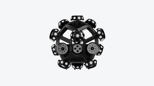
Training should be split by what each group actually needs to do with scan data. Quality technicians running high-volume part programs need a different skill set than quality engineers building inspection templates, and neither group needs the same depth as manufacturing engineers using scan data for root cause analysis.
A technician optimizing scan workflows for a 200-piece lot cares about fixture repeatability, scan path stability, and minimizing setup time between parts. A quality engineer customizing GD&T analysis for a new bracket design cares about datum alignment, tolerance zones, and report formatting that operators can read without a metrology background.
Cross-functional teams using scan data for continuous improvement care about trend visibility, CAD comparison outputs, and how to hand scan results to a machining cell without losing context.
Post-deployment reviews should run on a fixed cadence, not only when something breaks. A quarterly operational review is a reasonable starting point for most shops. The agenda should include three standing items. First, protocol adjustments for new part numbers.
When engineering releases a new casting or weldment, the scan setup from a similar past part may serve as a starting point, but tolerances, surface finish, and fixture access points change. Reviewing scan protocols before they become tribal knowledge prevents quality escapes and reduces setup time on the floor. Second, workflow bottlenecks.
If technicians report that scan data export is slowing downstream analysis, or that certain part geometries require excessive manual alignment, those issues need a documented action item. Third, compliance maintenance.
Laboratories working under ISO 17025 or similar quality system expectations need periodic evidence that scan procedures match documented methods, that software versions are controlled, and that any measurement uncertainty assumptions remain valid for the current part mix.
INSVISION supports this sustained-use model through role-aligned training programs and periodic operational reviews. The training tracks map to the actual division of labor in a Western manufacturing environment, where quality technicians, quality engineers, and process improvement teams all touch scan data but need different levels of depth.
The operational review structure helps plants connect alat scan 3D output to existing lean manufacturing and continuous improvement loops, rather than treating the scanner as an isolated inspection tool. That integration is what separates a scanner that gets used daily from one that sits under a dust cover after the initial validation project ends.
Scaling Alat Scan 3D Use Across Production Operations
Can a 3D scanning program really move from one quality lab into full production without falling apart? That is the question behind most failed scaling attempts. The hardware often works fine in isolation. The breakdown happens in the surrounding process: scan protocols that exist only in one technician’s head, inspection data scattered across local drives, and training that does not transfer between sites.
Scaling alat scan 3D use across production operations is therefore less about buying more scanners and more about building the infrastructure that makes multiple scanners behave like one system.
The first condition is protocol standardization. A scan used for first-article inspection in a metrology lab carries different assumptions than a scan taken next to an assembly line. Lighting, part temperature, fixture placement, and scan density all affect repeatability. Without a written protocol, two operators can measure the same casting and produce results that differ by more than the tolerance band.
Standardization means locking down scan path, exposure settings, alignment strategy, and reporting templates so that a quality engineer in one plant can trust data collected in another. This is not a software feature. It is a discipline.
Centralized data management matters just as much. When a global medical device manufacturer runs incoming quality control across three receiving facilities, the inspectable question is not simply whether a part passed locally. It is whether pass/fail decisions are consistent across sites, whether supplier trends are visible from a single dashboard, and whether raw point clouds are traceable to the batch record.
A folder of STL files on a shared drive cannot support that. The scanning system must be able to push data into a structured repository and, where needed, exchange information with MES or third-party databases. INSVISION systems support development of these interactions, which is exactly the kind of integration work that determines whether scanning becomes a production control method or remains an isolated measurement tool.
Phased deployment tends to work better than a big-bang rollout. A lean continuous improvement approach treats scanning expansion the same way it treats any process change: standardize one work cell, prove stability, then replicate. High-impact starting points include in-process inspection on automotive OEM assembly lines, where scan data can catch fit-up drift before subassemblies reach end-of-line audit;
spare part reverse engineering in aerospace MRO, where legacy components often lack CAD models and must be digitized for repair or replacement; and incoming inspection for medical device OEMs managing a global supplier base. Each scenario has different cycle time, surface finish, and accuracy requirements, but all share the need for a repeatable digital thread from scan to decision.
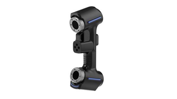
INSVISION’s industrial 3D scanning platform supports this phased expansion through consistent software and data structures across its hardware portfolio. A facility can begin with a single scanner in the quality lab, validate the workflow, then add units at receiving or on the line without rebuilding the entire inspection routine. The value is not in having more scanners.
It is in having more scanners producing comparable, auditable, actionable data. That is the point at which alat scan 3D stops being a metrology tool and becomes part of the production control system.
Hangzhou Insvision Technology Co., Ltd.
Address: Building 1, No. 1399 Liangmu Road, Yuhang District, Hangzhou, Zhejiang 311121, China
Copyright © Hangzhou Insvision Technology Co., Ltd. All rights reserved.
Copyright © Hangzhou Insvision Technology Co., Ltd. All rights reserved.