

3D Scanner Specifications Key Parameters, Working Principles, and Use Boundaries

What Are 3D Scanner Specifications? What Are 3D Scanner Specifications? 3D scanner specifications are the standardized technical parameters that quantify.
What Are 3D Scanner Specifications?
What Are 3D Scanner Specifications?
3D scanner specifications are the standardized technical parameters that quantify a scanning system’s performance, operational limits, and compatibility with industrial workflows. They define what a scanner can measure, how accurately it can measure it, and under what conditions it will function reliably.
Scenario Snapshot
A practical way to read the article is through this scenario:
- What Are 3D Scanner Specifications?: 3D scanner specifications are the standardized technical parameters that quantify a scanning system’s performance…
- Working Principles That Shape 3D Scanner Specificat…: A 3D scanner’s published specifications are not abstract marketing values.
- Key 3D Scanner Specifications for Industrial Evalua…: Industrial stakeholders reviewing 3D scanning systems often fixate on a single accuracy figure and ignore the surr…
Engineers and quality managers use these specifications to determine whether a given system can handle specific measurement tasks—such as verifying GD&T callouts on a machined casting or capturing surface geometry on a composite wing panel. Procurement teams rely on the same data to assess whether a scanner will integrate with existing quality management systems and inspection software.
Specifications act as a common technical language across industrial sectors. A metrology engineer in an automotive OEM plant, an MRO technician working on aerospace components, and a quality lead in a medical device facility all reference the same parameter categories: accuracy, resolution, scan speed, depth of field, and environmental tolerance.
Without this shared vocabulary, comparing systems or validating supplier claims becomes guesswork.
| Specification Category | What It Defines | Typical Industrial Relevance |
|---|---|---|
| Accuracy | Maximum deviation from true geometry | Determines suitability for tight-tolerance inspection (e.g., ±0.025 mm features) |
| Depth of Field | Working distance range for valid data capture | Affects setup flexibility on large or contoured parts |
| Scanning Area | Maximum measurable region per scan | Impacts throughput for large components such as airframe sections |
| Resolution | Smallest distinguishable feature size | Critical for capturing fine surface detail or small defects |
| Environmental Tolerance | Temperature, humidity, and particulate limits | Determines whether the scanner can operate on the shop floor or requires a controlled lab |
Alignment with ISO and ASME GD&T standards matters here. A scanner’s accuracy specification only becomes meaningful when it can be traced to accepted metrology practices. Specifications that omit reference to measurement standards or calibration procedures should raise immediate questions during technical evaluation.
Misunderstandings about specifications are common. A high accuracy rating under laboratory conditions does not guarantee the same performance next to a machining center with vibration and thermal drift. Similarly, resolution and accuracy are not interchangeable—a scanner can resolve fine features while still deviating from true geometry.
Reading specifications correctly means understanding the conditions attached to each value.
INSVISION, like other industrial metrology suppliers, publishes specification sheets structured around these parameter categories. The specifications serve as the basis for first-article inspection planning, gauge R&R studies, and correlation work between scanning data and CMM results.
Working Principles That Shape 3D Scanner Specifications
A 3D scanner’s published specifications are not abstract marketing values. They are the direct result of the underlying optical architecture, sensor geometry, and processing pipeline. Understanding this relationship helps engineers evaluate whether a given system can meet a tolerance stack-up or a first-article inspection requirement.
Laser triangulation systems project a laser line or point onto a surface. An offset camera observes the deformed line, and the system calculates depth from the known angle between emitter and sensor. Because the baseline and lens magnification are fixed, the measurable depth range—often called the depth of field—is physically constrained.
A scanner configured for fine detail will have a shallow depth of field, while one designed for larger parts trades resolution for range.
Structured light systems work differently. A projector casts a known pattern, typically a series of gray-coded or phase-shifted fringes, across the field of view. One or more cameras capture the deformed pattern from different angles. The software reconstructs 3D coordinates by matching each pixel to the projected pattern sequence.
Accuracy here depends on projector resolution, camera synchronization, and the calibration of the entire optical head.
Photogrammetry relies on multiple overlapping photographs of a part or scene. Feature matching algorithms identify common points across images, and bundle adjustment solves for camera positions and 3D coordinates simultaneously. This method scales to large assemblies but produces sparser point clouds than structured light unless supplemented with dense matching algorithms.
The table below summarizes how each technology maps to typical industrial applications.
| Technology | Accuracy Driver | Typical Depth of Field | Common Industrial Fit |
|---|---|---|---|
| Laser triangulation | Baseline distance, laser line thickness, sensor resolution | Shallow to moderate | High-precision small-part inspection, edge detection, deep grooves |
| Structured light | Projector pattern density, camera calibration, algorithm stability | Moderate | Dimensional verification of castings, forgings, and medium-sized components |
| Photogrammetry | Image overlap quality, target density, camera lens distortion correction | Large to very large | Large-assembly verification, airframe sections, jig and fixture alignment |
Depth of field values are not arbitrary. A scanner with a 650 mm depth of field, such as the INSVISION industrial 3D scanner scanner head, is engineered with optics and sensor placement that keep the laser line sufficiently focused across that entire range. By contrast, a photogrammetry-based tracker covering 2300 mm accepts lower point density in exchange for tracking a moving scanner over a much larger measurement volume.
Scanning area follows the same logic. A single structured light frame might cover 1100 mm × 800 mm, while a tracker with a wider baseline and lower magnification can register a 2600 mm × 2200 mm zone. These values derive from the field of view of the lenses, the working distance, and the resolution of the sensor array.
Processing algorithms also shape published specifications. Filtering, outlier removal, and surface smoothing can improve repeatability but may mask real surface texture. Engineers reviewing specifications should ask how accuracy is defined—whether as a single-frame volumetric error, a length measurement deviation against a calibrated artifact, or a statistical repeatability figure.
The answer reveals more about real-world performance than the headline number alone.
Key 3D Scanner Specifications for Industrial Evaluation
Industrial stakeholders reviewing 3D scanning systems often fixate on a single accuracy figure and ignore the surrounding parameters that determine whether that number holds up on a real production floor. That approach creates problems downstream. A scanner that performs well in a lab may struggle in a foundry, an MRO hangar, or a high-volume stamping line.
The more useful evaluation method is to group specifications by function and ask what each parameter means for the specific inspection or reverse-engineering task at hand.
Dimensional Performance
Measurement accuracy is the headline number, but it only matters when considered alongside scanning area and depth of field. A system claiming tight volumetric accuracy over a small field may require dozens of individual scans to cover a large casting, introducing cumulative alignment error. Depth of field becomes the limiting factor on parts with deep pockets, steep draft angles, or sudden changes in surface height.
Engineers working to GD&T callouts need to verify accuracy claims against the feature sizes they actually inspect, not just the manufacturer’s best-case specification.
Operational Range and Environmental Compatibility
Working distance determines whether a scanner can physically access the surfaces that need measuring. In aerospace MRO work, inspectors often scan installed components with limited clearance. On automotive assembly lines, the scanner may need to sit behind safety guarding while capturing body panels moving past on a conveyor.
Environmental ratings such as IP protection and operating temperature range tell you whether the system tolerates dust, coolant mist, humidity, or unconditioned factory air. A scanner without adequate sealing may drift or fail outright when ambient conditions change.
Connectivity, Data, and Safety
Data format support affects how easily scan output flows into CAD, CMM software, or a digital twin pipeline. Interface types matter when integrating with automated cells or networked inspection stations. Laser classification carries direct workplace safety implications: a Class 3R system may require controlled access areas or additional training, while lower classes simplify deployment in shared production spaces.
| Specification Category | Core Parameter | Industrial Relevance |
|---|---|---|
| Dimensional Performance | Measurement Accuracy | Defines the system’s ability to produce measurements that match true part dimensions, critical for meeting GD&T requirements in regulated sectors like medical devices and aerospace. |
| Dimensional Performance | Scanning Area | Describes the maximum surface area a system can capture in a single scan, impacting workflow efficiency for large parts such as automotive body panels or aerospace fuselage sections. |
| Dimensional Performance | Depth of Field | Indicates the range of distances from the scanner where measurements remain accurate, supporting scanning of parts with complex geometries or varying surface heights. |
| Operational Range | Working Distance | Specifies the distance range between the scanner and target part, important for use cases with limited access, such as on-site aerospace MRO inspections. |
| Environmental Compatibility | IP Protection Rating | Measures resistance to dust and moisture, determining suitability for use on factory floors, outdoor job sites, or harsh manufacturing environments. |
| Environmental Compatibility | Operating Temperature Range | Defines the temperature span where the system operates reliably, supporting use in unconditioned facilities or extreme climate conditions. |
| Connectivity & Data | Supported Data Formats | Lists the 3D file types the system can export, critical for seamless integration with CAD software, quality inspection tools, and digital thread pipelines in Industry 4.0 frameworks. |
| Connectivity & Data | Interface Types | Details the connection options (e.g., USB, Ethernet) for integrating the scanner with computers, network systems, or automated production lines. |
| Safety | Laser Classification | Indicates the laser safety level of the system, guiding compliance with workplace safety regulations in industrial settings. |
All parameter descriptions are general and applicable across industrial 3D scanning systems, with no brand-specific values presented in this section.
Use Boundaries for 3D Scanner Specifications
Use Boundaries for 3D Scanner Specifications
A published specification is not a universal guarantee. It is a performance boundary defined under controlled metrology conditions. For example, a documented accuracy figure assumes a stable thermal environment, a specific standoff distance, and a matte or prepared surface. When a part is shiny, hot, vibrating, or positioned at the edge of the scanner’s depth of field, the realized measurement uncertainty will shift.
Engineers should read 3D scanner specifications as upper-limit envelopes, not as constants that hold true in every inspection scenario.
The first boundary is scanning area versus part size. A system with a large measurement volume—such as a wide-area scanner used for body-in-white assembly or aerospace tooling verification—covers large surfaces quickly but typically trades away fine edge resolution.
Conversely, a scanner configured for small-part inspection delivers tight point spacing and high local precision, but it would be inefficient across a full vehicle frame. Matching the field of view to the largest dominant feature reduces the need for stitching multiple scans, which in turn lowers cumulative registration error.
Accuracy boundaries work the same way. A scanner rated for high single-scan precision is best applied to first-article inspection, GD&T callouts on machined features, or validation of injection-molded components with tight runout tolerances. The same instrument, used in a high-volume production line without environmental control, will not reproduce its laboratory-rated performance.
This distinction is critical for quality managers: a specification sheet tells you the boundary of what is possible under ideal conditions, while a gage R&R study on the actual production floor tells you what is repeatable in practice.
Depth of field sets another practical boundary. If a part has deep recesses, stepped surfaces, or complex curvature, the scanner must maintain focus and laser contrast across that entire height range. A system with a short depth of field may require multiple setups or robotic repositioning. A system with a longer depth of field can capture a taller feature in one pass, but may sacrifice resolution at the extremes.
Use the depth of field specification as a constraint on part geometry, not as a simple “more is better” metric.
The table below summarizes how three common specification boundaries map to typical inspection use cases.
| Specification Boundary | What It Defines | Typical Use Case Fit |
|---|---|---|
| Large scanning area | Coverage per single acquisition | Large-assembly verification, automotive body panels, aerospace tooling |
| High accuracy | Deviation from true geometry under controlled conditions | Small-part precision inspection, first-article inspection, GD&T validation |
| Long depth of field | Maintained focus across height variation | Castings, weldments, deep-draw stampings, complex brackets |
| Short depth of field with high resolution | Fine detail capture on limited Z-range | Medical device components, connector housings, small machined features |
Aligning these boundaries with the production environment supports lean manufacturing goals directly. When a scanner’s field of view matches the part envelope, inspection cycle time drops because fewer scans and alignments are needed. When the accuracy boundary matches the tolerance band of the part, false rejects and unnecessary rework decrease.
And when the depth of field covers the part’s actual Z-variation, operators avoid multiple setups that introduce operator-dependent variability. The result is a measurement process that is repeatable across shifts and production lines—without over-buying capability that the application cannot exploit.
A restrained example: INSVISION lists accuracy, scanning area, and depth of field as separate parameters for its tracking-based systems, with distinct values for the scanner unit and the tracker unit. That separation itself reflects the boundary logic—each component has its own operating envelope, and the overall system performance depends on how those envelopes interact in a given setup.
The misconception to avoid is treating any single specification as a summary of overall system quality. A scanner with excellent accuracy but a small scanning area is not “better” than a wide-area system with lower resolution. They occupy different boundaries. The evaluation task is to identify which boundaries matter for the specific part geometry, tolerance stack, and production cadence at hand.
Only then does the specification sheet become an engineering tool rather than a marketing artifact.
Common Misconceptions About 3D Scanner Specifications
Spec sheets for industrial 3D scanners are often read like fixed promises. In practice, the numbers describe performance under defined conditions, not universal behavior across every part, surface, and setup. Teams evaluating equipment for first-article inspection, reverse engineering, or in-line quality checks frequently carry assumptions into the review process that lead to mismatched expectations later.
Misconception 1: One Accuracy Rating Applies Everywhere
A published accuracy figure — say, up to 0.020 mm for a scanner — reflects the best achievable result under controlled conditions: optimal working distance, stable temperature, cooperative surface finish, and a part geometry that does not create steep viewing angles or deep occlusions.
Real parts rarely cooperate that cleanly. Accuracy degrades with distance from the scanner’s sweet spot. Glossy or matte black surfaces scatter or absorb light differently than the reference artifacts used during specification testing. Thin walls, deep pockets, and sharp edges introduce edge effects that published values do not capture.
A specification sheet may state accuracy as a single number, but that number is a ceiling, not a floor.
Industrial teams should treat accuracy as a function of the entire measurement setup, not a property of the scanner alone.
Misconception 2: Faster Scanning Means Better Performance
Scan speed is one of the most misunderstood parameters on a datasheet. Higher scan rates can reduce cycle time, but the relationship between speed and usable data quality is not linear.
Most scanners balance three competing factors: acquisition speed, point density, and accuracy. Pushing scan speed upward often forces a trade-off in resolution or measurement uncertainty. For a high-volume automotive stamping line checking GD&T callouts on every part, speed matters.
For aerospace MRO work measuring turbine blade wear against tight runout tolerances, point density and repeatability matter more than raw acquisition rate.
The right question is not “how fast does it scan?” but “how fast does it scan while still meeting the accuracy requirement for this specific inspection task?” Different applications demand different points on that curve.
Misconception 3: Specification Values Are Directly Comparable Across Vendors
Global standards for 3D metrology performance testing exist — ISO 10360 series and VDI/VDE 2634 are the most commonly referenced — but compliance is not always declared, and even when it is, the test conditions can differ. One vendor may state accuracy based on a specific artifact size and material. Another may use a different reference standard or environmental control protocol.
This creates a comparison problem. Two scanners can both list “0.020 mm accuracy” while achieving that value under meaningfully different test conditions. Teams should request the testing methodology behind published figures: which standard was used, what artifact was measured, what temperature range was maintained, and how many measurement points were collected.
The table below summarizes what a specification value does and does not tell you:
| Specification Parameter | What It Tells You | What It Does Not Tell You |
|---|---|---|
| Accuracy | Best-case measurement deviation under stated conditions | Performance on your part geometry, surface finish, or shop floor environment |
| Scan speed | Maximum acquisition rate in points or frames per second | Usable data quality at that speed for your tolerance requirements |
| Depth of field | Working distance range where the scanner functions | How accuracy varies across that range |
| Resolution | Minimum point spacing the scanner can achieve | Whether fine features on your parts will be captured reliably |
Why On-Site Validation Matters
Even a carefully read specification sheet cannot replace testing on your own parts in your own environment. Temperature swings, vibration from adjacent machinery, ambient lighting, and operator technique all influence real-world performance in ways datasheets cannot anticipate.
A practical validation approach involves scanning a representative part — ideally one with known GD&T dimensions from a CMM or calibrated reference — and comparing the scanner’s output against that baseline. Repeat the scan at different times of day, with different operators, and at different distances. The results reveal whether the specification holds up under production conditions.
Some suppliers, including INSVISION, support structured evaluation programs for industrial teams that need to verify scanner performance before committing to a purchase decision. The goal is not to replace specification review but to ground it in operational reality.
Specifications narrow the field. Validation confirms the choice.
Related Industrial Metrology Concepts
Related Industrial Metrology Concepts
Evaluating 3D scanner specifications in isolation misses the point. The practical value of accuracy, point density, and data format parameters becomes clear only when they are mapped to the inspection and quality systems already operating in a manufacturing environment.
GD&T Compliance
Geometric dimensioning and tolerancing (GD&T) under ISO 1101 and ASME Y14.5 defines how part features may deviate from nominal geometry. A 3D scanner’s ability to support GD&T verification depends on two specification categories. First, volumetric accuracy determines whether measured deviations fall within acceptable uncertainty bands for the tolerance being inspected.
Second, point density governs how well the scanner resolves small features such as fillet radii, edge breaks, and narrow slots. Sparse point clouds cannot reliably represent a tight profile tolerance or a small perpendicularity callout. Engineers reviewing scanner specifications for GD&T work should look beyond the headline accuracy number and confirm that resolution is adequate for the smallest feature size on the drawing.
First Article Inspection (FAI)
First article inspection requires documented evidence that a production process can produce parts conforming to specification. The output specifications of a 3D scanner—particularly data export formats, point cloud density, and measurement traceability—directly affect how smoothly FAI documentation is assembled.
Scanners that export dense, unprocessed point clouds into inspection software allow a quality engineer to generate color-mapped deviation reports tied to specific GD&T callouts. Because the raw scan data remains available, the measurement can be replayed, re-aligned, or re-evaluated without rescanning the part. This repeatability supports the traceability requirements common in aerospace and medical device FAI packages.
Digital Thread Integration
In an Industry 4.0 framework, inspection data should not terminate at a pass/fail report. Scan data feeds the digital thread when it is stored in standardized, open formats that downstream systems can consume. A typical flow links the scan point cloud to the CAD model, associates deviation values with specific part features, and stores the result in a quality management system or product lifecycle management platform.
The specification that matters here is less about accuracy and more about data structure: what file formats are supported, whether the scanner software preserves nominal-actual feature associations, and whether exported data can be consumed by third-party metrology software.
CMM Calibration Standards
Coordinate measuring machines are validated against international traceability frameworks such as ISO 10360. While 3D scanners are not CMMs, their performance specifications are increasingly validated using related principles—traceable length artifacts, reference spheres, and calibrated gauge blocks.
A scanner specification that states volumetric accuracy without reference to how that value was verified should be treated with caution. Buyers should ask whether the stated accuracy is traceable to a national metrology institute, what artifact was used for verification, and whether the specification applies across the full measurement volume or only at the center.
| Metrology Concept | Key Scanner Specification | Practical Impact |
|---|---|---|
| GD&T Compliance | Volumetric accuracy, point density | Determines which tolerance classes can be inspected reliably |
| First Article Inspection | Export formats, data traceability | Enables repeatable documentation for regulatory reporting |
| Digital Thread Integration | Standardized data formats, nominal-actual mapping | Allows scan data to flow into PLM, MES, and QMS systems |
| CMM Calibration Standards | Traceability statement, validation artifacts | Confirms stated accuracy is metrologically meaningful |
INSVISION approach to scanner specification documentation reflects this broader metrology context, with performance parameters stated alongside the validation methods used to confirm them.
INSVISION’s Approach to 3D Scanner Specification Design
In industrial metrology, specification sheets often obscure more than they reveal. A scanner rated for “high accuracy” under laboratory conditions may perform differently on a shop floor with temperature swings, vibration, and variable surface finishes. INSVISION addresses this by publishing specification parameters tied to defined operating conditions rather than ideal-case scenarios alone.
The company designs scanning and projection systems around verifiable values. Accuracy, working distance, depth of field, and scanning area are stated as measurable ranges, not single-point maxima. This approach lets quality engineers and manufacturing teams evaluate whether a given system can hold required tolerances across the full measurement volume, not just at the center of the field.
| Specification Parameter | Design Priority at INSVISION |
|---|---|
| Accuracy | Stated as an upper limit under defined conditions |
| Depth of field | Specified as a working range, not a single focal plane |
| Scanning area | Maximum field dimensions listed for both scanner and tracker components |
| Environmental rating | IP ratings and operating temperature/humidity ranges published |
| Data compatibility | Support for IGES, STP, DXF, DWG and major CAD/CAM workflows |
For projection systems used in composite layup and assembly guidance, INSVISION specifies projection accuracy, maximum projection angle, working distance, and laser class. Environmental ratings such as IP54 and operating temperature ranges account for deployment in production environments rather than metrology labs. Interface options include USB 3.0 and Ethernet, supporting integration into existing factory networks.
The specification philosophy is straightforward: industrial teams need data they can validate against their own gage R&R studies and part tolerances. Transparent, standards-aligned values reduce the gap between datasheet performance and real-world capability.
Frequently Asked Questions About 3D Scanner Specifications
Specification sheets for industrial 3D scanners can be difficult to interpret without a shared vocabulary. The questions below address the most common points of confusion raised by engineers, quality managers, and procurement teams evaluating metrology-grade scanning systems.
Q: How are 3D scanner accuracy specifications typically measured?
Accuracy is measured using calibrated reference artifacts — gauge blocks, ball bars, or certified step gauges — under controlled laboratory conditions. The scanner captures these artifacts, and the deviation between measured values and known reference dimensions is calculated. Testing follows ISO or ASME metrology standards to ensure traceability to national or international measurement institutes.
A specification like “up to 0.020 mm” refers to this laboratory performance envelope, not necessarily field performance. Always ask the vendor which standard was used, what artifact was measured, and whether the number represents a single-scan or multi-scan alignment result.
Q: What is the difference between scanning area and depth of field?
These two specifications are frequently conflated, but they describe different geometric boundaries.
| Specification | What It Describes | Typical Unit | Why It Matters |
|---|---|---|---|
| Scanning area | Maximum 2D surface area captured in one scan | mm × mm | Determines how many scans are needed to cover a part |
| Depth of field | 3D distance range where measurements stay within stated accuracy | mm | Defines how much surface height variation the scanner tolerates per scan |
A scanner may have a large scanning area but a shallow depth of field, meaning it captures wide, flat surfaces well but struggles with deep pockets or steep transitions. Conversely, a long depth of field is valuable for scanning parts with significant height variation without repositioning.
Q: How do environmental specifications impact on-site scanning performance?
Environmental specifications define the operating envelope where the scanner will perform reliably. Two parameters matter most: operating temperature range and ingress protection (IP) rating. Temperature affects sensor stability and thermal drift; a scanner specified for 15–30 °C may produce inconsistent results on a shop floor that fluctuates between 5 °C and 40 °C.
IP ratings indicate resistance to dust and moisture — critical for foundries, machining cells, or outdoor MRO work. Operating outside these parameters does not necessarily cause immediate failure, but measurement consistency and hardware longevity are not guaranteed. Procurement teams should compare environmental specs against the actual deployment environment, not ideal laboratory conditions.
Q: What data format specifications are most important for CAD integration?
Format compatibility determines whether scan data flows into design, inspection, and digital thread workflows without manual conversion steps. The core formats to confirm on any specification sheet include IGES and STEP for solid and surface CAD models, STL for mesh data used in inspection and reverse engineering, and DWG for 2D drawing integration. Some systems also support DXF for legacy CAD environments.
If the organization uses specialized composite or sheet metal software, verify compatibility with those specific formats. A scanner that exports only proprietary formats creates a data bottleneck that adds cost and time to every inspection cycle.
Q: Do laser classification specifications affect workplace safety compliance?
Yes. Laser class ratings align with workplace safety standards such as IEC 60825 and OSHA requirements in the United States. A Class 1 system is safe under all operating conditions and requires no additional controls. A Class 3R system, by contrast, is not safe for direct eye viewing and may require signage, training, or restricted access zones. The specification sheet should state the laser class clearly.
Quality and EHS teams must confirm the classification matches the operating environment and that local regulations permit the system’s use without additional safety engineering controls.
Summary of 3D Scanner Specification Fundamentals
A 3D scanner specification sheet is not a marketing brochure. It is a technical contract. For metrology engineers and quality managers, the listed values for accuracy, resolution, and volumetric limits define the boundary between a reliable measurement system and a source of non-conformance risk.
The core role of these specifications is to provide a standardized, repeatable framework for comparing hardware capabilities across different optical architectures and vendors.
The practical value of a specification parameter depends entirely on how it is derived. A volumetric accuracy figure only holds meaning when it is tied to a defined measurement standard, such as those outlined by VDI/VDE 2634 or ISO 10360.
In industrial deployment, aligning these values with specific use case requirements—whether that involves first-article inspection on a shop floor or inline verification of weldments—is critical. Ignoring the environmental envelope of a specification leads to measurement drift.
For example, a device calibrated for a controlled lab at 20°C will not maintain its stated accuracy near a heat-treat furnace without thermal compensation.
The table below outlines the primary specification categories engineers must evaluate against actual process requirements.
| Specification Category | Primary Evaluation Criterion | Typical Industrial Impact |
|---|---|---|
| Volumetric Accuracy | Deviation against traceable length standards | Determines suitability for tight GD&T callouts and pass/fail thresholds. |
| Resolution/Point Spacing | Minimum distinguishable feature size | Affects capture of sharp edges, radii, and surface texture details. |
| Depth of Field | Measurement volume depth (Z-axis range) | Dictates setup flexibility and ability to scan complex geometries without refocusing. |
| Environmental Tolerance | Temperature range and vibration resistance | Ensures stability on the production floor versus a metrology lab. |
Selecting hardware based purely on the smallest accuracy number often creates problems. A scanner with extremely tight accuracy but a narrow depth of field may be unusable for large castings or deep pockets. The specification framework only works when the user maps the parameter values to the physical constraints of the part and the cycle time of the process.
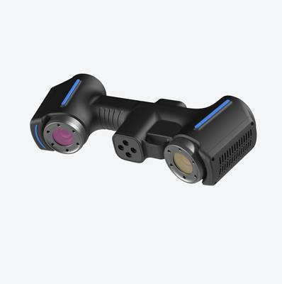
Beyond the hardware, a modern specification set must account for data integrity. The resolution of the point cloud is useless if the software pipeline cannot maintain traceability from the raw scan data to the final inspection report.
In the context of lean manufacturing and Industry 4.0, working with solution providers that prioritize transparent, standards-aligned specifications—such as INSVISION—supports smoother integration into existing quality management systems. This approach reduces the hidden costs associated with validating unverified accuracy claims and ensures that the digital twin generated by the scanner genuinely reflects the physical asset.
- What Is 3D Scanning? Principles, Workflow, and Industrial Applications 3D scanning is a digital measurement technology that converts the surface geometry of physical objects into 3D data. This entry covers its working principles, core parameters, industrial use cases, common misconceptions, and related technical…
- What Is a 3D Scanner? Types, Parameters, and Selection Criteria A 3D scanner captures three-dimensional surface data from physical objects and converts geometry, dimensions, and features into digital data for inspection, reverse engineering, and modeling.
- What Is 3D Scanning Accuracy? Accuracy, Repeatability, and Resolution Explained 3D scanning accuracy describes how closely scan data matches an object's actual geometry and dimensions. It is assessed through local accuracy, volumetric accuracy, stitching accuracy, repeatability, and resolution.
- What Is Point Cloud Data? Point Clouds, Meshes, and CAD Models in 3D Scanning Point cloud data is an important raw data format in 3D scanning. It consists of discrete 3D coordinate points that describe object surface geometry and support inspection, reverse engineering, modeling, and archiving.
Hangzhou Insvision Technology Co., Ltd.
Address: Building 1, No. 1399 Liangmu Road, Yuhang District, Hangzhou, Zhejiang 311121, China
Copyright © Hangzhou Insvision Technology Co., Ltd. All rights reserved.
Copyright © Hangzhou Insvision Technology Co., Ltd. All rights reserved.