

How to Evaluate clone 3D scanner for Inspection
clone 3d scanner: Shop-Floor Context and Measurement Needs Most shops still treat measurement as a gate at the end of the line.
Shop-Floor Context and Measurement Needs
Most shops still treat measurement as a gate at the end of the line. That assumption quietly breaks down once tolerances tighten, batch sizes shrink, and suppliers demand digital proof instead of paper sign-offs. The real pressure on the shop floor is not just catching bad parts. It is getting enough trustworthy dimensional data early enough to correct the process before scrap accumulates.
Capability and Deployment Mapping
| Focus Area | Decision Point | Deployment Note |
|---|---|---|
| Shop-Floor Context and Measurement Needs | Most shops still treat measurement as a gate at the end of the line. | That assumption quietly breaks down once tolerances tighten, batch sizes shrink, and suppliers demand digital proof instead of paper sign-offs. |
| Where Traditional Measurement Breaks Down | Most shops still assume a 3D scanner captures everything in one pass. | That assumption dies quickly on real parts. |
| How 3D Scanning Fits the Workflow | The real shift in industrial metrology isn’t just about faster scanners. | It’s about how scan data moves through the rest of the operation. |
| Validation Points Before Deployment | The value of a clone 3D scanner in production depends less on the hardware than on how well the site conditions match the measurement task. | Teams that treat deployment as a plug-and-play event usually discover the mismatch during first-article inspection, when the cost of correction… |
Production engineers now face overlapping demands. First-article inspection has to move faster because setup time counts against OEE. In-process checks must work next to machine tools, under mixed lighting, without a climate-controlled lab. And quality managers need records that survive customer audits, not handwritten notes stapled to a traveler.
Legacy tools miss on both speed and coverage. A CMM gives precise points but is too slow for broad surface inspection. Hand gauges are quick but capture only a few features. Neither produces the dense point cloud that lets a team compare the as-built part to CAD and see exactly where springback, weld distortion, or fixture drift moved material.
This is why the conversation has shifted toward portable 3D scanning. A clone 3D scanner workflow, in the sense of capturing and reproducing complex geometry digitally, fits the shop-floor reality: scan where the part sits, process the mesh, and push results back to engineering.
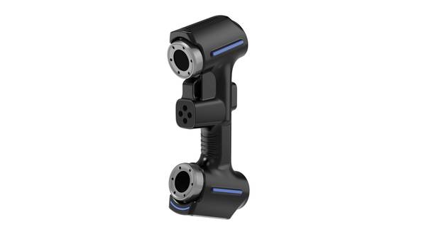
INSVISION builds its industrial 3D scanner category around that same logic, with systems designed for accuracy up to 0.020 mm and scanning areas reaching 1100 mm by 800 mm. Those numbers matter less as marketing claims and more as evidence that the equipment can hold its own near the machine, not just in the lab.
The workflow needs better data because downstream decisions are only as good as the measurements behind them. A scanner that captures thousands of points per pass gives process engineers something a gauge never can: a full picture of form deviation, not just a pass-fail light.
Where Traditional Measurement Breaks Down
Most shops still assume a 3D scanner captures everything in one pass. That assumption dies quickly on real parts. Deep pockets, steep draft angles, undercut features, internal bore transitions—these areas defeat a fixed scan path. The scanner either loses line of sight or the laser return weakens, so the software fills gaps with interpolation. What looks like a complete mesh on screen may be partly guessed geometry.
For a quality manager checking GD&T callouts against a CAD model, guessed geometry is worse than missing data because it passes visual review.
Data continuity creates a second failure point. When an operator pauses to reposition the part or scanner, the new scan must align to the existing coordinate system. Small drift compounds across multiple setups. On a large weldment or composite layup tool, that drift can exceed the tolerance band before anyone notices. The result is a clean-looking dataset that does not reflect the physical part.
Delivery rhythm compounds both problems. First-article inspection, supplier qualification, and MRO teardown all run on deadlines. If the scan workflow requires excessive fixturing, repeated alignment, or manual post-processing to close mesh holes, the bottleneck shifts from measurement to data preparation.
An INSVISION industrial 3D scanner addresses this through wider scan coverage and tracking that maintains coordinate continuity across repositioning. The practical question is not whether a scanner can capture the easy surfaces. It is whether the system can hold accuracy through the transitions, because that is where traditional measurement quietly falls apart.

How 3D Scanning Fits the Workflow
How 3D Scanning Fits the Workflow
The real shift in industrial metrology isn’t just about faster scanners. It’s about how scan data moves through the rest of the operation. A few years ago, 3D scanning lived in a lab. Someone brought parts in, scanned them, exported a mesh, and sent a PDF to quality. Now the conversation has changed.
Manufacturers want the scan to sit inside the same loop as CAD, CNC programming, first-article inspection, and supplier corrective actions. That changes what a scanner has to be.
A usable process usually breaks into four connected stages: capture, compare, review, and report. Capture is the field step. The part may be on a fixture, a machine bed, or still mounted in an assembly. The scanner has to reach it without excessive staging. For larger parts, a tracker-based setup helps. INSVISION’s industrial 3D scanner, for example, separates scanner and tracker depth of field.
The scanner holds up to 0.020 mm accuracy while the tracker handles a working volume large enough for structures up to 2600 mm by 2200 mm. That matters when the scan object cannot be moved to a lab.
Comparison is where most of the engineering value appears. The scan mesh is aligned to nominal CAD or to a golden part. Deviation maps show form error, twist, weld shrinkage, or springback. Review is the step people often skip when buying hardware. The scan file has to be readable by people who never touch the scanner: design engineers, quality managers, external auditors. Reporting closes the loop.
A report that links deviation values to GD&T callouts or customer requirements is far more useful than a color map with no context.
The workflow works when the scanner software exports data that downstream systems can consume. That means standard mesh formats, clean alignment reports, and comparison outputs that can be attached to an NCR or PPAP package. Some shops still treat scan data as a standalone inspection event. The more mature approach treats it as an input to a broader quality record.
For Western manufacturers, the workflow question often comes up during a supplier quality crisis or a first-article failure. A Tier 1 supplier might need to prove dimensional stability across a batch. Scanning a single part gives a snapshot. Scanning several parts and comparing them to the same reference shows drift. The difference is not hardware capability;
it’s whether the scan process is repeatable enough to be part of an audit trail.
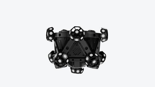
INSVISION positions its industrial 3D scanners around this connected workflow rather than around a single capture spec. The accuracy numbers are useful, but the practical test is whether the scan-to-report sequence can run without a dedicated metrology specialist at every step. That is the direction many shops are heading: scanning as a routine manufacturing step, not a lab event.
Validation Points Before Deployment
Validation Points Before Deployment
The value of a clone 3D scanner in production depends less on the hardware than on how well the site conditions match the measurement task. Teams that treat deployment as a plug-and-play event usually discover the mismatch during first-article inspection, when the cost of correction is highest.
Start by confirming the scan volume against the largest feature envelope you expect to capture. If your work spans small castings and large weldments, verify that the scanner’s depth of field and scanning area cover both extremes without repositioning the part more than your workflow tolerates.
For a system like INSVISION’s industrial 3D scanner, the scanner side offers up to 0.020 mm accuracy and a scanning area up to 1100 mm × 800 mm, while the tracker extends tracking range and a wider capture window. Those numbers matter only if your parts fit inside them comfortably.
Next, check environmental stability. Temperature swings, vibration from nearby machining, and inconsistent lighting can degrade repeatability in ways that a spec sheet will not show. Run a short repeatability study on site: scan the same feature set three times across an hour and compare deviations. If the spread exceeds your tolerance band, fix the environment before blaming the equipment.
Also validate data flow. The scan file must move into your CAD or inspection software without manual rework. Confirm export formats and whether your GD&T callouts survive the translation. A scanner that measures well but forces engineers to rebuild features manually creates a hidden bottleneck.

Finally, verify operator readiness. The system should not depend on one trained specialist. Document the scan path, alignment strategy, and acceptance criteria so a second operator can reproduce results. INSVISION’s approach fits best where teams need traceable dimensional data across mixed part sizes and want to reduce the gap between scanning and actionable inspection.
Deployment succeeds when the scanner, the site, and the process agree before production starts.
Hangzhou Insvision Technology Co., Ltd.
Address: Building 1, No. 1399 Liangmu Road, Yuhang District, Hangzhou, Zhejiang 311121, China
Copyright © Hangzhou Insvision Technology Co., Ltd. All rights reserved.
Copyright © Hangzhou Insvision Technology Co., Ltd. All rights reserved.