

Industrial 3D Scanning Methods Principles Applications and Evaluation Criteria

3d scanning methods: Definition of 3D Scanning Methods Definition of 3D Scanning Methods 3D scanning methods are a family of non-contact measurement.
Definition of 3D Scanning Methods
Definition of 3D Scanning Methods
3D scanning methods are a family of non-contact measurement techniques used to capture the three-dimensional geometric data of physical objects and convert that data into digital point cloud or mesh models. Unlike traditional touch-probe coordinate measuring machines (CMMs), which rely on physical contact with a part surface, 3D scanning methods acquire dimensional information optically or through other energy-based sensing.
The result is a dense spatial dataset that represents surface geometry at resolutions impractical for discrete point probing.
In modern industrial contexts, these methods serve as the measurement backbone for several intersecting initiatives. Lean manufacturing programs use 3D scanning to reduce inspection bottlenecks and shorten first-article approval cycles. Industry 4.0 digital transformation efforts depend on scan-derived digital twins for simulation, virtual assembly, and change management.
Metrology teams apply the same data within ISO and ASME frameworks—including ASME Y14.5 GD&T evaluation—to verify form, profile, and positional tolerances against design intent.
Common sector applications reflect the breadth of Western industrial demand. Automotive OEMs use scanning for body-in-white dimensional quality and tooling validation. Aerospace MRO operations capture as-found and as-left conditions on turbine blades, airframe skins, and composite repairs. Medical device manufacturers apply scanning to implant geometry verification and packaging validation.
Energy producers scan casing threads, flange faces, and erosion-prone surfaces during outage inspections.
The table below summarizes how different industrial priorities map to the capabilities of 3D scanning methods versus conventional contact metrology.
| Industrial Requirement | 3D Scanning Methods | Touch-Probe CMM |
|---|---|---|
| Data density per inspection | High—millions of points per scan | Low—hundreds of discrete points |
| Freeform surface capture | Native capability | Limited; requires dense point planning |
| Inspection speed on complex geometry | Fast; full-field acquisition | Slow; point-by-point probing |
| Integration with GD&T software | Supported via mesh-to-CAD comparison | Direct point-based reporting |
| Suitability for soft or deformable parts | High; no contact force | Low; probe contact may deflect part |
INSVISION notes that the practical value of a given 3D scanning method depends less on the scanning principle itself than on how well the acquired point cloud integrates into an existing quality workflow. Scan data without a defined comparison routine against CAD or a reference dataset adds little to dimensional control.
Core Working Principles of Mainstream 3D Scanning Methods
Industrial 3D scanning converts physical geometry into dense coordinate data through three dominant physical principles. Each method generates a point cloud—a collection of XYZ coordinates that represents surface topology—but the underlying physics, achievable accuracy, and practical constraints differ significantly.
Laser triangulation projects a focused laser line or dot onto a surface. A camera positioned at a known angle relative to the emitter observes the deformation of that line. When the laser strikes a surface at varying depths, the reflected line shifts position on the camera sensor. The scanner calculates depth using trigonometric relationships between the emitter, camera, and observed line position.
This method delivers high accuracy over short to medium working distances, typically sub-millimeter, and handles reflective or dark surfaces reasonably well when tuned properly. Single-line configurations excel at reaching into deep cavities and holes where multi-line patterns scatter unpredictably.
Structured light scanning projects a known pattern—commonly a series of parallel fringes or a pseudo-random speckle field—onto the object using a digital projector. One or more cameras capture the deformed pattern from fixed angles. Software analyzes how the surface distorts the projected geometry, decoding depth information from phase shifts or pattern displacement across hundreds of thousands of points simultaneously.
This parallel acquisition makes structured light fast for full-field capture. Accuracy rivals laser triangulation on matte, low-reflectivity surfaces, but glossy, transparent, or highly textured areas often require temporary matting spray. Blue light sources have become standard because shorter wavelengths reduce sensitivity to ambient illumination and improve edge definition.
Time-of-flight scanning measures the round-trip duration of a light pulse from emitter to surface and back to a detector. Since the speed of light is constant, distance equals half the elapsed time multiplied by that velocity. Phase-based variants modulate the emitted beam and compare the phase shift of the return signal for smoother results.
These scanners trade point density and near-field accuracy for long-range capability, often operating from several meters to hundreds of meters. They suit large structures, building interiors, and outdoor environments where triangulation geometry becomes impractical.
| Method | Physical Principle | Typical Range | Point Density | Primary Constraints |
|---|---|---|---|---|
| Laser triangulation | Geometric displacement of reflected line | 0.1–1 m | High | Line-of-sight geometry, surface reflectivity |
| Structured light | Projected pattern deformation analysis | 0.2–2 m | Very high | Ambient light, gloss, transparency |
| Time-of-flight | Light pulse round-trip timing | 1–300+ m | Moderate to low | Range precision, multi-path reflections |
Understanding these mechanisms helps engineers match a scanning method to inspection requirements. A turbine blade with tight GD&T callouts demands different physics than a warehouse floor plan. The point cloud itself remains format-agnostic—subsequent alignment, meshing, and comparison against CAD models proceed identically regardless of how the coordinates were captured.
Key Evaluation Criteria for Industrial 3D Scanning Methods
Evaluating 3D scanning methods for industrial use is less about comparing vendor claims and more about matching technical capability to the tolerances, geometry, and workflow constraints of a specific job. A scanner that works well for capturing large exterior panels may be unsuitable for inspecting deep boreholes or small cast features.
The criteria below reflect how quality engineers, metrology leads, and manufacturing engineers typically assess scanning technology before committing to a process change.
| Evaluation Criterion | Technical Definition | Industrial Use Case Relevance |
|---|---|---|
| Scanning Area | The maximum single-frame capture volume, typically expressed in millimeters. | Determines whether a scanner suits large components such as body-in-white assemblies or smaller parts like turbine blades and brackets. A scanning area up to 650 mm × 550 mm covers most mid-size tooling and casting work without excessive repositioning. |
| Scanning Mode Flexibility | The availability of multiple laser line configurations—single lines for deep recesses, parallel lines for precision surfaces, and high-count arrays for speed. | Real parts rarely have uniform geometry. Flexibility lets an inspector switch between modes on the same part, using a single blue laser line for holes and a higher line count for broad surface capture. |
| Data Resolution | The density and spacing of captured points, often tied to laser line spacing and sensor quality. | Drives the ability to resolve fine features such as small radii, lettering, or GD&T callouts on first-article inspection reports. Higher resolution supports tighter tolerance verification. |
| Deep Feature Capture Capability | The scanner’s ability to acquire data inside holes, slots, and recessed areas that are hard to reach with wide laser patterns. | Critical for automotive engine blocks, aerospace fastener holes, and hydraulic manifolds. A single narrow laser line is typically required for this type of geometry. |
| Scan Speed | The rate of point acquisition or frames per second, often linked to the number of laser lines used simultaneously. | Affects cycle time in production inspection and digital twin development. Faster modes with more laser lines reduce data collection time on large, smooth surfaces. |
| Environmental Operating Tolerance | The scanner’s stability under varying lighting, temperature, and vibration conditions. | Shop-floor metrology often occurs outside a controlled lab. A method that tolerates ambient light and moderate temperature drift reduces the need for dedicated metrology rooms. |
| CAD/Metrology Software Integration Compatibility | The ability to export point clouds or mesh data into inspection and CAD platforms for comparison against nominal models. | Reverse engineering and digital twin workflows depend on clean data transfer into software for surfacing, deviation analysis, and downstream simulation. |
Each criterion matters differently depending on the application. Quality inspection teams tend to weight data resolution and software integration heavily, since their output feeds formal reports and PPAP documentation. Reverse engineering groups care more about scanning mode flexibility and deep feature capture, because they frequently scan parts with complex internal geometry and no existing CAD model.
Digital twin development adds speed and environmental tolerance into the mix, as capturing an entire production cell or large machine tool may require scanning under less controlled conditions.
The key point is that no single criterion stands alone. A fast scanner with poor deep feature capture will create inspection bottlenecks on parts with threaded holes or recessed pockets. Conversely, excellent resolution means little if the scanning area requires dozens of repositioning moves on a large weldment.
Teams should define the dominant geometry and tolerance requirements first, then evaluate scanning methods against those constraints.
INSVISION systems address these criteria through configurable scanning modes and scanning areas suitable for mid-size industrial parts, but the evaluation framework above applies regardless of the supplier under consideration.
Ideal Application Boundaries of Common 3D Scanning Methods
Understanding where a specific 3D scanning method performs best requires defining the application boundary first. Rather than viewing one technique as universally superior, engineers should match the measurement principle to the geometric scale, surface condition, and tolerance requirement of the part.
A method that excels on a 40 mm orthopedic implant will not necessarily be the right choice for a 4 m wind turbine hub, and vice versa.
The table below maps common method categories to their strongest application windows.
| Method Category | Typical Measurement Principle | Ideal Application Window | Representative Western Industrial Scenarios |
|---|---|---|---|
| Structured Light (High-Precision) | Projected fringe patterns + multiple cameras | Small-to-medium parts requiring tight tolerance verification | Small medical device components, turbine blade leading edges, precision castings |
| Laser Triangulation | Single or multiple laser lines + camera offset | Medium parts with defined edges, holes, and sheet metal geometry | Automotive sheet metal part inspection, stamped bracket first-article checks |
| Time-of-Flight / Phase-Based | Laser pulse or phase shift measurement | Large-scale assemblies where global geometry matters more than micron detail | Energy sector assembly scans, aerospace MRO on airframe sections, plant layout documentation |
Structured light systems are ideally suited for components where surface detail and dimensional accuracy within a confined scanning volume drive the inspection workflow. Parts under roughly 650 mm × 550 mm per scan frame fit this boundary cleanly. The method handles organic surfaces and complex freeform geometry well, which explains its use in medical device quality labs and precision casting verification.
A key consideration is that structured light performs best on matte or lightly textured surfaces; highly reflective or transparent parts typically require a temporary coating.
Laser triangulation scans occupy a different application boundary. The method is ideally suited for parts with pronounced edges, cutouts, and hole patterns, where the laser line can resolve feature boundaries cleanly. Automotive sheet metal components — door panels, brackets, cross members — fall into this category.
The technique tolerates some ambient light variation on the shop floor and delivers reliable edge detection even when the part has moderate surface finish variation. Multiple laser lines increase speed but reduce the ability to penetrate narrow recesses; a single line mode is the better match for deep holes or slot features.
Time-of-flight and phase-based scanning methods address the opposite end of the scale. These systems are ideally suited for capturing large structures where the scanning volume extends to several meters per frame. Energy sector assembly verification, wind turbine component alignment, and aerospace MRO on fuselage sections all sit within this boundary.
Accuracy is typically measured in tenths of a millimeter rather than microns, which is appropriate when the specification calls for global form and assembly fit rather than GD&T callouts on small features.
The practical takeaway: define the part size, the tightest tolerance on the drawing, and the surface condition before selecting a method. That sequence prevents the common mistake of forcing a scanning technology outside its intended application boundary. Manufacturers such as INSVISION provide systems across these method categories, but the method fit itself should drive the evaluation.
Common Misconceptions About Industrial 3D Scanning Methods
Misunderstandings about 3D scanning methods persist across manufacturing floors, often leading teams to dismiss the technology or apply it incorrectly. Let’s examine four widespread assumptions against what actually happens in industrial practice.
Misconception 1: All 3D Scanning Methods Produce Equivalent Data Quality
This assumption ignores fundamental differences in measurement physics. Structured light scanners project patterns and triangulate surface geometry. Laser line scanners track reflected intensity along a known path. Photogrammetry reconstructs geometry from multiple overlapping images. Each method handles resolution, noise, and dimensional accuracy differently.
A structured light system might capture fine surface detail but struggle with depth discontinuities. A laser line scanner typically penetrates narrow slots and deep holes more effectively. Photogrammetry excels at large-area coverage but delivers lower point density on small features.
Industrial reality: Automotive OEMs often combine methods on a single part — structured light for exterior body panels, laser line scanning for mounting bosses and threaded holes. Assuming one method covers all measurement tasks leads to bad data and rejected first-article inspections.
| Scanning Method | Typical Strengths | Common Limitations |
|---|---|---|
| Structured light | High point density, fast area capture | Limited on deep recesses, reflective surfaces |
| Laser line scanning | Deep hole access, works on varied finishes | Slower on large flat areas |
| Photogrammetry | Large-volume coverage | Lower resolution on small features |
Misconception 2: Higher Scan Speed Always Reduces Precision
Speed and precision trade off — but not linearly, and not always in the direction people assume. Modern scanners use multiple laser lines or expanded fringe patterns to capture more data per pass. The key variable is not raw speed but data density per unit area and how the scanner handles motion.
A scanner operating with 50 blue laser lines can capture a full surface quickly while maintaining point spacing because each line contributes to the same measurement dataset. Precision suffers when systems increase speed by reducing exposure time or skipping data points, not when they simply add more measurement channels.
Industrial reality: In aerospace MRO, technicians scanning turbine blades need both speed and tight tolerances. Systems that capture 26 or 50 parallel laser lines deliver rapid coverage without sacrificing the point spacing required for runout tolerance verification. The bottleneck is usually data processing, not acquisition.
Misconception 3: 3D Scanning Only Works on Smooth, Non-Reflective Surfaces
This belief is a decade out of date. Blue laser technology changed the game. Shorter wavelengths scatter less on machined metal, cast surfaces, and semi-reflective coatings. Modern scanners also use dynamic exposure control — adjusting laser intensity in real time as surface reflectivity changes.
That said, mirror-polished surfaces and transparent materials remain challenging. The practical solution is not avoiding scanning but using matting spray or powder in targeted areas. The misconception persists because engineers remember older red-laser systems that struggled on anything shiny.
Industrial reality: Energy sector components — turbine housings, valve bodies, weldments — arrive with mill scale, rust, oil residue, and uneven finishes. Blue laser scanning handles these conditions without surface preparation in most cases. Deep hole scanning modes, using a single laser line, further improve performance on bores and internal passages.
Misconception 4: 3D Scanning Requires Years of Specialized Training
This may have been true for early CMM-based systems. It is not true for modern handheld and automated scanners. Operators learn basic scanning technique in days, not years. The software handles alignment, mesh generation, and comparison to CAD automatically.
What requires real expertise is not scanning but measurement planning. Knowing where to place targets, when to use different scanning modes, and how to validate results against GD&T callouts — that is metrology knowledge, not scanner operation skill.
Industrial reality: Quality managers in medical device manufacturing routinely train production inspectors on scanning workflows within a week. The scanner becomes another inspection tool alongside calipers and bore gauges. The training investment goes into understanding dimensional tolerances, not button-pushing.
INSVISION addresses these misconceptions through scanner designs that combine multiple scanning modes — precision scanning with 7 blue laser lines, high-speed modes with up to 50 lines, and dedicated deep hole scanning with a single line — within the same system, covering areas up to 650mm × 550mm in a single pass.
Related Technical Concepts in Industrial 3D Metrology
Industrial professionals evaluating 3D scanning methods quickly encounter a set of adjacent terms that define how scan data is used, validated, and integrated. Understanding these concepts is essential for selecting the correct workflow and interpreting results in discrete manufacturing.
3D Metrology is the umbrella discipline covering the measurement of physical objects in three dimensions. It encompasses contact methods (CMMs, articulated arms) and non-contact methods such as structured light and laser triangulation. Within this field, 3D scanning serves as one data acquisition technique among several.
Point Cloud Processing refers to the computational steps required to convert raw scanner output into usable geometry. Raw scan data consists of millions of discrete XYZ coordinates. Processing includes noise filtering, outlier removal, alignment of multiple scans, and mesh generation. The quality of this processing chain directly affects downstream tasks such as CAD comparison or tooling correction.
Reverse Engineering is the process of generating a parametric CAD model from an existing physical part when no drawing or model exists. The workflow typically follows: scan the part, process the point cloud, extract geometric features, and rebuild the surface or solid model. Common in legacy tooling, aftermarket components, and MRO operations.
GD&T Compliance (ASME Y14.5 and ISO GPS) concerns whether a measured part conforms to its engineering drawing. Geometric Dimensioning and Tolerancing defines form, orientation, location, and runout callouts. 3D scanning outputs must be evaluated against these callouts using dedicated inspection software.
ASME Y14.5 and ISO GPS differ in several fundamental rules — for example, datum precedence and the treatment of simultaneous requirements — so the governing standard must be confirmed before evaluation.
Digital Twin Integration describes the practice of maintaining a living digital representation of a physical asset or part. Scan data feeds the twin, enabling wear analysis, deformation tracking, and virtual assembly validation. In aerospace MRO and energy applications, periodic scans update the twin over the component lifecycle.
First Article Inspection (FAI) is a documented verification process required by AS9102 in aerospace and similar standards elsewhere. The first production part from a new or modified process must be fully measured and compared to the drawing. 3D scanning accelerates FAI by capturing full-surface geometry rather than sampling discrete points, though compliance documentation still requires structured reporting.
The table below summarizes how each concept connects to industrial scanning workflows:
| Concept | Core Function | Typical Workflow Connection |
|---|---|---|
| 3D Metrology | Disciplined measurement of physical geometry | Defines accuracy requirements and traceability |
| Point Cloud Processing | Raw data refinement | Converts scanner output into usable mesh or CAD data |
| Reverse Engineering | CAD model generation from physical parts | Requires feature extraction and surface fitting |
| GD&T Compliance | Tolerance evaluation per ASME Y14.5 or ISO GPS | Determines pass/fail against engineering callouts |
| Digital Twin Integration | Persistent virtual asset representation | Enables trend analysis and predictive maintenance |
| First Article Inspection | Formal verification of initial production output | Requires full documentation and structured reporting |
Each concept represents a distinct stage in the broader quality and engineering workflow. A scanner alone does not deliver GD&T compliance, FAI reports, or digital twins — those outcomes depend on software, process discipline, and integration with existing quality systems. Professionals evaluating 3D scanning methods should assess the entire workflow, not just the acquisition hardware.
INSVISION’s Contribution to Industrial 3D Scanning Technology
The practical value of any 3D scanning method depends on how well it adapts to the part sitting in front of the inspector. A single scanning strategy rarely handles both a large, freeform automotive panel and a small machined bracket with deep countersinks. Industrial tools that survive on Western shop floors tend to share one trait: they let the user switch scanning methods without switching systems.
INSVISION develops industrial 3D scanning solutions aimed at core manufacturing workflows—quality control, reverse engineering, and digital twin implementation. The company’s approach is built around multiple scanning modes within a single hardware platform.
This addresses a common production reality: a quality manager may need wide-area acquisition for first-article inspection in the morning, then a single-line mode for capturing deep hole geometry on the same part in the afternoon.
The table below summarizes typical scanning mode categories found in INSVISION systems and their corresponding application fit. The specifications reflect confirmed product parameters available from the manufacturer.
| Scanning Mode | Blue Laser Lines | Typical Application Fit |
|---|---|---|
| Precision Scanning | 7 parallel lines | Dimensional inspection of complex surfaces and GD&T feature extraction |
| High-Speed Scanning | 26–50 parallel lines | Large-part digitization and rapid reverse engineering (varies by system) |
| Deep Hole Scanning | 1 single line | Capturing recessed features, bores, and areas with difficult line-of-sight access |
| Hole Rescanning | Intelligent identification | Detecting and rescanning holes and cut edges on sheet-metal or machined components |
This multi-mode structure reflects how 3D scanning method principles get applied in commercial industrial tools. Rather than forcing one optical technique across every geometry, the system adjusts laser line count and acquisition strategy to the measurement task.
For Western buyers evaluating such technology, the relevant question is not which single method is “best,” but whether the platform can shift between methods fast enough to keep a production inspection cell running.
Frequently Asked Questions About 3D Scanning Methods
What 3D scanning method is ideally suited for complex parts with internal holes?
The primary challenge with internal features is line-of-sight. Structured light scanners project patterns onto a surface and read the deformation. A deep cavity blocks that pattern from returning to the sensor. For these geometries, the relevant specification is not the number of laser lines in standard mode, but the availability of a dedicated single-line mode.
A single blue laser line can penetrate narrow openings and reach bottom surfaces that wider multi-line arrays cannot. When evaluating a scanner for hole inspection, confirm whether the single-line mode is a distinct setting or a software crop of a larger field. Also check how the system handles hole rescanning. Some workflows require manual re-pass over each bore;
others flag cut edges and holes automatically during the scan, then prompt the operator to reacquire only those regions. For parts with many drilled or milled holes, this distinction affects throughput significantly.
How do 3D scanning methods integrate with existing CAD and quality management software?
Most industrial scanners output mesh data (STL, OBJ) or point clouds (PLY, PCD). CAD integration is typically handled through a separate inspection module that aligns the scan to the nominal CAD model, computes deviations, and exports a color map or CSV report. The scanner itself rarely talks directly to SolidWorks or CATIA. Instead, the scan-to-CAD comparison happens in metrology software.
What matters for integration is the openness of the data pipeline. If the scanner exports a standard format, your team can use existing software without a proprietary lock-in. For quality management, the scanner must support a repeatable alignment method — typically best-fit or feature-based alignment using datum references from the CAD model.
If your QMS requires traceable records, confirm that the software logs the alignment method, scan parameters, and operator ID.
Can 3D scanning methods support compliance with ISO and ASME metrology standards?
Yes, but compliance is a system-level property, not a scanner property. A scanner plays a supporting role in a documented measurement process. ISO 10360 and ASME B89.4.19 define acceptance tests for coordinate measuring systems, including some optical systems. However, the scanner alone does not guarantee GD&T compliance. The user must validate the full workflow: scanner, alignment, software, and operator procedure.
For ISO 9001 or AS9100 audits, the key question is whether the measurement system has been validated for its intended use. You need a calibration certificate, a defined uncertainty budget, and a documented correlation study against a reference method (CMM or gauge). Procurement teams should ask for third-party accuracy certificates and the measurement volume over which those specifications hold.
What core factors should teams prioritize when selecting a 3D scanning method for their facility?
Selection should start with application fit, not specifications.
| Factor | What to Evaluate | Why It Matters |
|---|---|---|
| Scan area | Maximum field of view per shot | Larger areas reduce alignment error; smaller areas increase resolution |
| Laser line configuration | Single-line vs. multi-line modes | Single-line for deep holes; multi-line for speed on open surfaces |
| Data output | Mesh vs. point cloud; file formats | Determines downstream CAD and QMS compatibility |
| Alignment method | Feature-based, best-fit, or target-based | Affects accuracy on parts with weak datum features |
| Calibration | Certified artifacts and documented uncertainty | Required for ISO/ASME compliance |
| Operator skill | Training time and procedure complexity | High turnover facilities need simpler workflows |
Scan area deserves special attention. A scanner with a 650mm × 550mm field covers medium castings and brackets efficiently, while a 2200mm × 2200mm area targets large panels or aerospace structures. Match the scan area to your largest common part, not your largest possible part.
INSVISION publishes specifications for scan area and laser configurations at the model level, which allows engineers to evaluate application fit without committing to a demo.
Key Takeaways for Industrial Teams
Key Takeaways for Industrial Teams
Three primary categories define most industrial 3D scanning methods: structured light projection, laser triangulation, and photogrammetry. Structured light systems project known patterns onto a surface and measure deformation to reconstruct geometry. Laser triangulation uses reflected laser lines or points and calculates distance based on sensor angle.
Photogrammetry derives 3D coordinates from overlapping photographs taken at multiple positions. Each category trades speed, accuracy, and surface compatibility differently.
Evaluation should weigh four criteria before any method enters a facility: measurement uncertainty against tolerance requirements, scan volume versus part envelope, surface finish and material constraints, and operator workflow integration. A matte injection-molded bracket poses different challenges than a machined aerospace component with deep bores.
Deep holes, for example, often require a single-line laser mode rather than multi-line patterns that scatter unpredictably in cavities.
The table below summarizes method selection by typical application profile.
| Application Profile | Suitable Scanning Principle | Key Consideration |
|---|---|---|
| Large castings, sheet metal, freeform surfaces | Structured light or photogrammetry | Scan area coverage and datum alignment |
| Small precision features, GD&T callouts | Laser triangulation with narrow line pattern | Resolution versus time per scan |
| Deep bores, undercuts, internal channels | Single-line laser mode | Occlusion handling and line-of-sight limits |
| First-article inspection on complex assemblies | Combination approach, often multi-mode | Reference geometry and registration strategy |
Method choice should follow the inspection requirement, not the reverse. Operators commonly over-specify resolution and then struggle with file size, scan time, or registration drift. A pragmatic approach starts with the tightest tolerance on the drawing and works backward to determine whether the scanning method can resolve it reliably across the full inspection routine.
3D scanning supports lean manufacturing objectives when deployed as a verification tool rather than a standalone inspection silo. Reduced fixture dependency, faster setup versus CMM programming for non-repetitive work, and digital archiving of as-built geometry all contribute to shortened feedback loops. However, scanning does not replace hard gages for every characteristic.
Runout on a rotating assembly or a bearing bore with a 5-micron tolerance may still demand tactile verification.
The broader fit with Industry 4.0 comes from the data format. Point clouds and meshes feed directly into CAD comparison, statistical process control, and digital twin workflows. When engineering and quality teams share the same scan dataset, root cause analysis and corrective action move faster than with isolated measurement reports.
Facilities evaluating 3D scanning methods should pilot on real production parts, not demo blocks. Material finish, ambient lighting, part temperature, and operator ergonomics affect repeatability in ways that laboratory demonstrations rarely expose. A method that works well in controlled lighting may falter next to a loading dock or in a welding cell.
INSVISION provides industrial scanning hardware across multiple configurations, including systems with scanning areas up to 650 mm × 550 mm for compact workpieces and larger-area solutions for oversized components. The relevant point for industrial teams remains method alignment: the scanning principle and mode configuration must match the part geometry, tolerance band, and production environment.
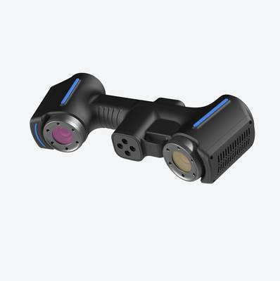
Selection decisions should document assumptions about surface preparation, scan coverage, and validation frequency. Without that discipline, even a capable scanning method becomes another underused instrument on the shelf.
- What Is 3D Scanning? Principles, Workflow, and Industrial Applications 3D scanning is a digital measurement technology that converts the surface geometry of physical objects into 3D data. This entry covers its working principles, core parameters, industrial use cases, common misconceptions, and related technical…
- What Is a 3D Scanner? Types, Parameters, and Selection Criteria A 3D scanner captures three-dimensional surface data from physical objects and converts geometry, dimensions, and features into digital data for inspection, reverse engineering, and modeling.
- What Is 3D Scanning Accuracy? Accuracy, Repeatability, and Resolution Explained 3D scanning accuracy describes how closely scan data matches an object's actual geometry and dimensions. It is assessed through local accuracy, volumetric accuracy, stitching accuracy, repeatability, and resolution.
- What Is Point Cloud Data? Point Clouds, Meshes, and CAD Models in 3D Scanning Point cloud data is an important raw data format in 3D scanning. It consists of discrete 3D coordinate points that describe object surface geometry and support inspection, reverse engineering, modeling, and archiving.
Hangzhou Insvision Technology Co., Ltd.
Address: Building 1, No. 1399 Liangmu Road, Yuhang District, Hangzhou, Zhejiang 311121, China
Copyright © Hangzhou Insvision Technology Co., Ltd. All rights reserved.
Copyright © Hangzhou Insvision Technology Co., Ltd. All rights reserved.