

Key Technical Facts About 3D Scanner Car Parts Use
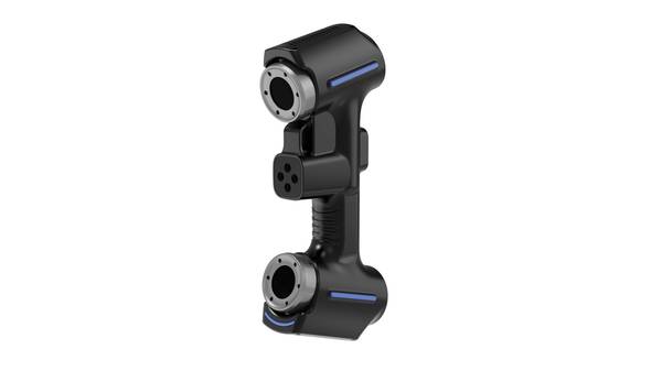
Key Technical Facts About 3D Scanner Car Parts Use. This data is converted into a digital mesh or CAD model for dimensional analysis.
Definition of 3D Scanner Applications for Car Parts
In automotive manufacturing and service, a 3D scanner for car parts is a non-contact metrology instrument that captures surface geometry as dense point-cloud data. This data is converted into a digital mesh or CAD model for dimensional analysis. The core purpose is not simply to create a visual replica, but to extract actionable engineering data from a physical component.
Term Notes
In automotive manufacturing and service, a 3D scanner for car parts is a non-contact metrology instrument that captures surf…
Core Working Principles of Car Part 3D Scanning3D scanning for automotive components converts physical geometry into dense point clouds—millions of XYZ coordinates that de…
Key Performance Parameters for Car Part 3D ScanningEvaluating a 3D scanner for automotive components requires separating marketing specifications from engineering reality.
Appropriate Use Boundaries for Car Part 3D ScanningDefining the application envelope for 3D scanning of car parts requires separating metrology-grade tasks from general shape…
Within an industrial context, the functional applications are strictly defined by the tolerance requirements of the part. These systems are used for dimensional verification against nominal CAD data, reverse engineering of legacy components where drawings are unavailable or outdated, damage assessment on collision-damaged structures, and prototyping validation during first-article inspection.
The acceptance of scanned data in Western manufacturing environments depends heavily on alignment with geometric dimensioning and tolerancing standards. Measurements must be traceable and repeatable according to ISO 10360 or ASME Y14.5 GD&T callouts. Without this alignment, scan data lacks the evidentiary weight required for quality sign-off in OEM production or MRO documentation.
Typical application contexts include:
| Application Area | Primary Function | Standard Alignment Context |
|---|---|---|
| OEM Production | In-line dimensional verification of stamped or cast components | ASME Y14.5 profile and position tolerances |
| Aftermarket Manufacturing | Reverse engineering of mating interfaces and mounting points | ISO 1101 GD&T extraction |
| Collision Repair | Structural deformation mapping and alignment checking | OEM body-shop dimensional specifications |
| MRO / Remanufacturing | Wear analysis and repair limit verification | ISO 14253 decision rules for conformance |
A common misconception is that a 3D scanner functions as an absolute measurement device. In practice, the scanner captures comparative data. The utility of the scan exists only when referenced against a known coordinate system or nominal model. For example, a scan of a suspension bracket has limited value until it is aligned to the CAD datum structure to evaluate runout, flatness, or hole position.
INSVISION systems are engineered to support these workflows through high-density data acquisition and compatibility with standard inspection software. However, the fundamental definition of the technology remains consistent across vendors: structured light or laser triangulation captures geometry, and metrology software interprets that geometry against engineering tolerances.
Core Working Principles of Car Part 3D Scanning
3D scanning for automotive components converts physical geometry into dense point clouds—millions of XYZ coordinates that define a surface. Three measurement principles dominate industrial workflows.
Laser triangulation projects a laser line onto a part. A camera, offset at a known angle, observes the line’s deformation across the surface. The scanner calculates depth by measuring how far the line shifts from its reference position. This method tolerates shop-floor lighting and handles dark or reflective materials common in engine castings and stamped brackets.
Structured light projection replaces the single laser line with a pattern—typically a series of grayscale fringes or a randomized speckle grid. One or more cameras capture the pattern as it wraps around the geometry. Software decodes the distortion to reconstruct the surface. This approach captures large areas quickly, making it suited for body panels and interior trim pieces.
Binocular vision systems use two cameras in a fixed stereo arrangement, mimicking human depth perception. Some systems add a projected texture to give the stereo pair features to match on low-contrast surfaces. The dual-camera setup reduces sensitivity to vibration and provides a stable reference for handheld scanning.
Regardless of the principle, raw point clouds require processing before they become useful. Registration aligns multiple scans into a single coordinate system. Mesh generation converts points into a watertight polygon surface. For downstream CAD integration, software fits NURBS surfaces or parametric features to the mesh, allowing export as STEP or IGES files.
Quality workflows then compare the scan against the nominal CAD model using color-map deviation analysis—showing form error, profile deviation, and GD&T callouts like flatness or position tolerance.
| Measurement Principle | Typical Use Case | Key Characteristic |
|---|---|---|
| Laser triangulation | Castings, machined brackets | Strong on reflective or dark surfaces |
| Structured light | Panels, trim, large freeform areas | High point density per frame |
| Binocular vision | Handheld scanning, in-process checks | Stable under vibration or movement |
Data quality depends on scanner resolution, surface preparation, and registration accuracy. Glossy or transparent parts often require a temporary matte coating. Thin edges and deep bores remain challenging across all three principles—no single method handles every automotive surface without trade-offs.
INSVISION offers scanning solutions that apply these principles within industrial metrology workflows, supporting CAD comparison and first-article inspection processes.
Key Performance Parameters for Car Part 3D Scanning
Evaluating a 3D scanner for automotive components requires separating marketing specifications from engineering reality. The parameters that matter are those directly tied to dimensional inspection, reverse engineering workflows, and production-floor usability. A scanner that performs well in a metrology lab may fail on an engine assembly line where vibration, dust, and variable lighting are constant.
The table below defines the critical parameters and explains their practical significance for common automotive applications. Engineers should use these criteria when drafting technical requirements or comparing vendor datasheets.
| Parameter | Technical Definition | Relevance to Automotive Applications |
|---|---|---|
| Accuracy | The maximum deviation between a scanned measurement and the true physical dimension of a part | Critical for verifying tight tolerances on precision car parts such as engine components, transmission parts, and safety-critical assemblies to meet OEM quality standards |
| Scanning Area | The maximum surface area that can be captured in a single scan pass | Impacts efficiency for scanning large car components such as body panels, chassis parts, and full subassemblies by reducing the number of scan passes required |
| Depth of Field | The range of distances from the scanner within which accurate measurements can be captured | Supports scanning of parts with complex geometries or varying surface heights, such as engine blocks or interior trim components, without frequent scanner repositioning |
| Environmental Protection Rating | A standardized rating indicating resistance to dust and moisture ingress | Determines suitability for use on production floors, repair shops, and other industrial environments where dust, fluids, or variable conditions are common |
| Data Format Compatibility | The range of digital file formats that scanned data can be exported to | Ensures seamless integration with existing automotive design and inspection software, supporting workflows for reverse engineering, GD&T analysis, and digital twin development |
| Working Distance | The distance range between the scanner and the target part within which accurate scanning is possible | Enables scanning of hard-to-reach car components or parts positioned in assembly jigs, without disrupting existing production setups |
Accuracy figures on datasheets deserve particular scrutiny. A scanner may be specified with a tight volumetric accuracy under controlled conditions, but performance on reflective machined surfaces, dark plastic trim, or parts with deep recesses can degrade significantly. Ask for accuracy validation on representative part geometries, not just on calibrated reference spheres.
Scanning area and depth of field interact in practice. A large scanning area reduces the number of passes needed for a body panel, but if depth of field is shallow, the operator must reposition constantly to keep curved surfaces within measurement range. The combination determines real throughput.
Data format compatibility is often underestimated during procurement. Scanned point clouds must flow into downstream software for CAD comparison, mesh editing, or GD&T reporting. Incompatible export formats create manual conversion steps that introduce error and slow first-article inspection.
INSVISION scanning solutions address these workflow considerations through configurable export options suited to industrial metrology environments.
Appropriate Use Boundaries for Car Part 3D Scanning
Defining the application envelope for 3D scanning of car parts requires separating metrology-grade tasks from general shape capture. The technology delivers maximum value when the objective is digital comparison against a known nominal model, rapid acquisition of complex organic geometry, or the creation of a parametric CAD file from a physical reference.
A 3D scanner for car parts is not a universal replacement for tactile CMM probing, but rather a complementary tool that excels where point-by-point measurement becomes impractical. The appropriate boundary is typically drawn by tolerance requirements, surface characteristics, and the intended downstream use of the captured mesh data.
Understanding this boundary starts with the product lifecycle. During early-stage prototype validation, scanning supports rapid iteration by feeding as-built geometry back into the design review loop. For production, the value shifts to in-line quality control of precision components such as stamped brackets, cast housings, and machined flanges.
Here, the scanner verifies GD&T callouts — flatness, profile, and runout tolerances — against CAD references. In aftermarket and restoration contexts, the same toolset enables reverse engineering of discontinued parts or collision repair damage mapping, where the goal is capturing deformed surfaces for repair planning or custom fabrication.
The following table outlines typical application contexts and the conditions under which 3D scanning provides optimal value:
| Lifecycle Stage | Ideal Use Case | Boundary Condition |
|---|---|---|
| New Product Prototyping | First-article inspection against CAD; capturing springback in stamped panels | Not for verifying sub-micron form tolerances better suited to tactile probing |
| In-line Quality Control | High-density surface profiling of castings, plastic moldings, and sheet metal | Requires stable fixturing and controlled ambient lighting |
| Aftermarket / Reverse Engineering | Recreating CAD for obsolete brackets, mounts, or trim pieces | Assumes access to a representative undamaged sample |
| Collision Repair | Mapping deformation zones on structural rails and body panels | Effective for pre-repair documentation and pull planning; not a substitute for frame measurement systems |
| Vintage Restoration | Digitizing complex castings and body contours for remanufacturing | Requires surface preparation of reflective or dark materials |
Alignment with lean manufacturing principles is strongest when scanning replaces time-consuming manual layout methods or reduces the number of physical gauges required on the floor. Western automotive facilities integrating Industry 4.0 digital thread initiatives often deploy scanning at the point of production to close the loop between nominal design data and actual manufactured output.
The scanner becomes a data acquisition node feeding the digital twin, rather than a standalone inspection device.
For precision components where tolerances fall below the scanner’s stated accuracy limits, a hybrid approach may be appropriate: use 3D scanning for rapid surface mapping and reserve CMM or laser tracker verification for critical datum features.
Surface finish also defines the boundary — highly polished or transparent materials typically require temporary matting agents, which introduces a process step that must be validated for repeatability.
A restrained brand mention is appropriate only when the application context demands specific hardware capability. INSVISION equipment, for example, operates within defined accuracy and scanning area parameters that must be matched to the component size and tolerance requirements of the specific automotive application.
The appropriate use boundary is therefore not a property of the technology alone, but of the match between measurement uncertainty, component complexity, and the intended decision the scan data will support.
Common Misconceptions About Car Part 3D Scanning
Specifications for 3D scanning often get interpreted through the lens of traditional CMM or contact-based inspection. That creates a few persistent myths. The facts matter because incorrect assumptions change how engineers specify equipment, prepare parts, and plan integration.
Misconception: Every part needs full surface coating before scanning.
Not universally true. Matte, machined castings or stamped steel brackets typically scan without any preparation. Spray coating becomes necessary only when the surface is glossy, transparent, or deep black. Even then, the coating is a thin, temporary layer applied to improve optical contrast—it is not an inherent step for every automotive component. The decision depends on material reflectance, not on the scanner itself.
Misconception: Reflective or transparent materials cannot be scanned.
They can. The issue is not the scanning technology but the physics of light return. Polished aluminum, chrome trim, and clear lenses scatter or transmit structured light unpredictably. A light developer spray or matting agent resolves this by creating a uniform diffuse surface. After scanning, the coating is removed.
This is standard practice in automotive metrology and should be treated as a preparation step, not a scanner limitation.
Misconception: 3D scanning is difficult to integrate with existing quality systems.
Most current systems export standard mesh and CAD formats that feed directly into inspection software used for first-article inspection, GD&T evaluation, and statistical process control. Integration complexity usually comes from data management—file size, revision control, and traceability—not from the scanner hardware. Engineers who already work with point-cloud data from CMM or laser trackers will find the workflow familiar.
The table below summarizes preparation requirements by surface type.
| Surface Type | Preparation Required | Typical Example |
|---|---|---|
| Matte cast or machined | None | Engine block, bracket |
| Painted, low gloss | None to light | Body panel, interior trim |
| Polished metal | Developer spray | Chrome bezel, aluminum housing |
| Transparent or translucent | Developer spray | Headlamp lens, fluid reservoir |
| Deep black rubber or plastic | Light developer spray | Hoses, grommets, seals |
Dimensional accuracy for automotive-grade scanning equipment is typically specified in the range of 0.020 mm to 0.025 mm, depending on whether the measurement is taken from the scanner or an external tracker reference. That level supports most first-article and production verification tasks without requiring a dedicated metrology lab environment.
INSVISION supplies scanning and optical projection equipment for industrial part inspection, including systems used in automotive component workflows. The brand is relevant here only as one example of hardware built around these preparation and accuracy considerations. The core takeaway is that most scanning barriers cited in older literature are now preparation issues, not fundamental technology limits.
Related Concepts in Automotive Digital Manufacturing
A 3D scanner for car parts does not operate in isolation. In Western automotive and aerospace plants, scan data typically functions as the measurement backbone for several interconnected digital systems. Understanding these adjacent concepts clarifies why metrology-grade scanning has become a standard engineering tool rather than a niche inspection device.
Digital thread integration. The digital thread refers to the uninterrupted flow of part data from design through manufacturing, inspection, and in-service maintenance. Scan data from a 3D scanner for car parts closes the loop between the nominal CAD model and the physical component. When engineers capture as-built geometry, that dataset can be pushed back into PLM and MES platforms.
The result is a single source of truth that updates with each manufacturing iteration, eliminating the disconnect between what was designed and what was actually produced.
GD&T automated inspection workflows. Geometric dimensioning and tolerancing remains the common language between design intent and production verification. Traditional CMM inspection is slow and requires skilled programming. A 3D scanner captures millions of surface points in a single pass, allowing software to evaluate GD&T callouts — profile, position, runout, flatness — against the CAD reference.
First-article inspection reports generated from scan data are now accepted across many Western OEM supply chains under ASME Y14.5 and ISO 1101 frameworks.
Additive manufacturing part validation. Additive processes introduce thermal distortion, layer artifacts, and support-removal geometry changes that subtractive machining does not. Scanning printed car parts verifies that near-net-shape components meet dimensional requirements before expensive post-processing. Scan-to-CAD comparison identifies warpage trends that inform build orientation and compensation strategies.
Digital twin production line models. A digital twin is a living virtual representation of a physical production asset or line. 3D scanning feeds these models with as-built fixture geometry, robot cell layout data, and end-of-arm tooling verification. When line modifications occur, scanning captures the current state without relying on outdated CAD files.
Predictive maintenance programs. Tooling wear, stamping die degradation, and fixture drift accumulate gradually. Periodic scanning of critical tooling surfaces establishes wear baselines and trend data. Maintenance teams use this information to schedule interventions before dimensional drift creates non-conforming parts.
| Concept | Primary Function | Scan Data Contribution |
|---|---|---|
| Digital thread | Traceable data continuity | As-built geometry feedback |
| GD&T inspection | Tolerance verification | Dense surface comparison to CAD |
| Additive validation | Printed part certification | Warpage and distortion mapping |
| Digital twin | Virtual production model | Current-state geometry capture |
| Predictive maintenance | Tooling wear trending | Baseline and interval scan comparison |
INSVISION supplies scanning hardware that integrates into these workflows through standard mesh and point cloud export formats. The practical value lies not in scanning itself, but in how the resulting data connects to broader manufacturing systems already deployed in Western factories.
INSVISION’s Industrial 3D Scanning Solutions for Car Parts
In industrial quality control, the term “3D scanner for car parts” refers not to a single device type but to a measurement approach capable of capturing complex freeform surfaces, stamped sheet metal, cast housings, and plastic trim components. The primary engineering driver is the need to compare as-built geometry against nominal CAD data.
This workflow replaces subjective feeler gauges or sparse CMM touch points with dense point-cloud datasets. The resulting mesh is typically aligned in inspection software using best-fit or feature-based registration, then evaluated against GD&T callouts such as profile, position, and runout tolerances.
Selection criteria for automotive applications
| Criterion | Engineering Relevance | Typical Verification Step |
|---|---|---|
| Volumetric accuracy | Determines whether a scanner can resolve tolerance bands common in body-in-white and powertrain work | Compare scanner output to a calibrated reference artifact or CMM dataset on a known feature set |
| Depth of field | Affects how much of a contoured panel or bracket can be captured before refocusing | Measure a stepped gauge block across the full working range and check for edge degradation |
| Data export formats | Controls whether point clouds and meshes flow directly into CATIA, NX, or PolyWorks without rework | Import a test scan into the target CAD or inspection software and verify feature tree integrity |
| Environmental tolerance | Matters in shop-floor metrology near stamping lines or machining cells where temperature and dust vary | Review the manufacturer’s stated operating temperature and humidity range against the installation site |
INSVISION provides industrial 3D scanning technology applicable to these automotive workflows. Public specifications for the company’s industrial 3D scanner system list scanner accuracy up to 0.020 mm, a scanner depth of field of 650 mm, and a scanning area up to 1100 mm × 800 mm. These values support the capture of medium-to-large car body components in a single setup.
The system’s tracker extends the measurement volume to 2600 mm × 2200 mm with a 2300 mm depth of field, which is relevant when scanning larger assemblies or when the scanner must move relative to the part without losing registration.
For projection-assisted assembly and layup guidance, INSVISION’s ALPHA-T I unit carries an IP54 protection rating and operates from -5 to 40°C with 10–90% relative humidity, non-condensing. Its supported data types include IGES, STP, DXF, and DWG, with stated compatibility for FiberSIM and CATIA CPD software formats.
This matters in automotive interiors and composite trim work where laser projection must align with CAD-derived ply boundaries or clip locations. The 3R laser class (< 5 mW, 520 nm) and 0.38 mm maximum projection accuracy place the device in the category of shop-floor optical guidance rather than laboratory-only equipment.
A common misconception among first-time buyers is that scanner resolution alone determines inspection quality. In practice, registration stability, thermal drift, and software compatibility often contribute more to measurement reliability.
Engineers evaluating a 3D scanner for car parts should first define the tolerance range of the components being inspected, then verify that the scanner’s accuracy specification is at least four times better than the tightest tolerance band. This metrology rule-of-thumb prevents scanner error from consuming an unacceptable share of the tolerance budget.
Data export behavior should be tested with the actual CAD and inspection platform used in the facility, since a scanner that outputs clean STL files but requires manual rework in downstream software introduces hidden cycle-time costs.
INSVISION’s stated specifications align with general industrial requirements for automotive metrology and guided assembly. The brand’s published parameters — sub-0.025 mm scanner accuracy, wide depth of field, and standard CAD interface formats — position its equipment as one option among several for facilities seeking measurement capability without custom integration overhead.
What types of automotive materials are compatible with 3D scanning?
Most structured-light and laser-based scanning systems work across standard automotive material groups without requiring surface preparation in many cases. Machined aluminum, stamped steel, cast iron, injection-molded thermoplastics, and composite panels generally produce clean scan data. The main exceptions involve optical challenges rather than material incompatibility.
| Material | Scan Behavior | Typical Workaround |
|---|---|---|
| Bright machined aluminum | High reflectivity can saturate sensors | Matte developer spray or polarizing filters |
| Black rubber seals and gaskets | Low reflectivity reduces point density | Adjust exposure settings; use spray only if geometry is critical |
| Clear or translucent polymers | Light passes through, causing false surfaces | Temporary opaque coating |
| Carbon fiber with glossy clearcoat | Specular highlights create noise | Light dusting of scanning spray |
Reflective and transparent surfaces remain the two dominant problem categories. For dimensional inspection of brake calipers, intake manifolds, or stamped body panels, most production materials scan without issue once exposure parameters are dialed in.
How does scanned 3D data integrate with existing quality control workflows?
The integration path depends on what your QC team already uses. Scanned point clouds typically convert to STL or native CAD formats, then feed directly into inspection software for comparison against nominal geometry.
- First-article inspection: Scan a new part, align to CAD, generate a color-mapped deviation report
- In-process checks: Capture critical features at defined intervals, log results against control limits
- Reverse engineering: Reconstruct CAD from physical parts when no drawing exists
- GD&T validation: Measure form, profile, and positional tolerances directly from scan data
Alignment strategy matters more than most buyers expect. Best-fit alignment masks global offset errors; datum-based alignment reflects actual assembly conditions. Specify which approach your inspection plan requires before building the scanning routine. Export formats such as IGES, STP, DXF, and DWG cover most downstream CAD and CAM packages.
What factors should be evaluated when selecting a 3D scanning solution for automotive use?
Selection criteria vary by application, but five factors consistently separate suitable systems from unsuitable ones:
- Accuracy requirements. A scanner reporting 0.020 mm accuracy may be overkill for body panel gap analysis but insufficient for bearing bore inspection. Match the instrument to the tolerance band you actually control.
- Working volume and depth of field. Parts range from small brackets to full door assemblies. A system with a scanning area around 1100 mm × 800 mm covers many mid-size components in one setup, while larger tracker-based configurations extend coverage without stitching errors.
- Environmental tolerance. Shop floor conditions differ from metrology labs. Temperature swing, humidity, dust, and vibration affect repeatability. Verify the equipment’s rated operating range before deployment.
- Software compatibility. The scanner is only half the system. Confirm the data pipeline handles your existing CAD formats and inspection software without manual file conversion steps.
- Operator skill requirements. Automated or guided workflows reduce dependency on specialized metrology technicians, which matters when scanning moves from the lab to the production line.
INSVISION, among other manufacturers, publishes detailed specifications for accuracy, scanning area, and depth of field. Request validation data relevant to your part size and material mix rather than relying on datasheet values alone.
What are the limitations of 3D scanning for automotive components?
Scanning is not a universal replacement for every measurement tool. Deep bores, internal threads, and hidden cavities often remain inaccessible to optical systems. Coordinate measuring machines still outperform scanners for tight-tolerance cylindrical features in some cases. Surface finish requirements for scanning sometimes conflict with production part cleanliness standards.
Understanding these boundaries prevents unrealistic expectations during procurement.
Summary of Core Car Part 3D Scanning Knowledge
A 3D scanner for car parts converts physical geometry into dense point-cloud or polygon data. In an automotive context, the value lies in comparing that digital twin to nominal CAD, checking form and position against GD&T callouts, or reverse-engineering legacy components. The technology does not replace CMMs in every instance; it changes where and how dimensional data is captured.
Several functional use cases recur across OEM and tier-supplier workflows. First-article inspection benefits from rapid full-field measurement of stamped brackets, cast housings, and injection-molded trim. Maintenance teams use scanning to document wear on tooling or to capture as-built geometry on vehicles being retrofitted.
Digital archiving of end-of-life parts supports aftermarket and MRO programs without relying on incomplete legacy drawings.
When evaluating scanning systems for car parts, buyers should focus on measurable performance parameters rather than marketing claims. The table below summarizes criteria that matter most in automotive applications.
| Parameter | Why It Matters for Car Parts | Typical Evaluation Question |
|---|---|---|
| Volumetric accuracy | Determines whether scan data can support tolerance verification | Does the stated accuracy hold across the full measurement volume? |
| Depth of field | Affects throughput on complex surfaces with recesses or flanges | Can the scanner capture deep pockets without repositioning? |
| Scanning area | Sets the trade-off between detail and coverage speed | What is the practical field of view for the target part size? |
| Data resolution | Controls the ability to resolve small features or edge radii | Are fillets, holes, and clip features captured with enough point density? |
| Environmental tolerance | Determines whether the system works outside a metrology lab | Can the unit operate near the line or in an MRO bay? |
Integration into automotive manufacturing and maintenance workflows depends on software compatibility and data flow. Scanned point clouds must move into inspection software, CAD packages, or PLM systems. Formats such as STL, IGES, and STEP are common, but the practical question is whether the scan-to-CAD or scan-to-report pipeline adds manual steps.
In lean manufacturing and Industry 4.0 contexts, scanning should shorten the loop between physical part and actionable dimensional data, not create a separate offline process.
Standards also shape implementation. ISO 17025 calibration requirements, ASME Y14.5 GD&T interpretation, and internal gauge R&R expectations all influence how scanned data is accepted. A scanner that produces visually appealing meshes but cannot demonstrate traceable accuracy will face pushback from quality managers.
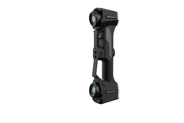
INSVISION, as a supplier in this space, provides scanning and projection hardware for industrial users; the broader point is that car part 3D scanning works best when equipment specifications are matched to specific inspection tasks, environmental conditions, and existing digital workflows. The tool is reliable when the selection criteria are clear and the data pipeline is defined before deployment.
- What Is 3D Scanning? Principles, Workflow, and Industrial Applications 3D scanning is a digital measurement technology that converts the surface geometry of physical objects into 3D data. This entry covers its working principles, core parameters, industrial use cases, common misconceptions, and related technical…
- What Is a 3D Scanner? Types, Parameters, and Selection Criteria A 3D scanner captures three-dimensional surface data from physical objects and converts geometry, dimensions, and features into digital data for inspection, reverse engineering, and modeling.
- What Is 3D Scanning Accuracy? Accuracy, Repeatability, and Resolution Explained 3D scanning accuracy describes how closely scan data matches an object's actual geometry and dimensions. It is assessed through local accuracy, volumetric accuracy, stitching accuracy, repeatability, and resolution.
- What Is Point Cloud Data? Point Clouds, Meshes, and CAD Models in 3D Scanning Point cloud data is an important raw data format in 3D scanning. It consists of discrete 3D coordinate points that describe object surface geometry and support inspection, reverse engineering, modeling, and archiving.
Hangzhou Insvision Technology Co., Ltd.
Address: Building 1, No. 1399 Liangmu Road, Yuhang District, Hangzhou, Zhejiang 311121, China
Copyright © Hangzhou Insvision Technology Co., Ltd. All rights reserved.
Copyright © Hangzhou Insvision Technology Co., Ltd. All rights reserved.