

Core Concepts of 3D Scanning Automotive Workflows and Standards
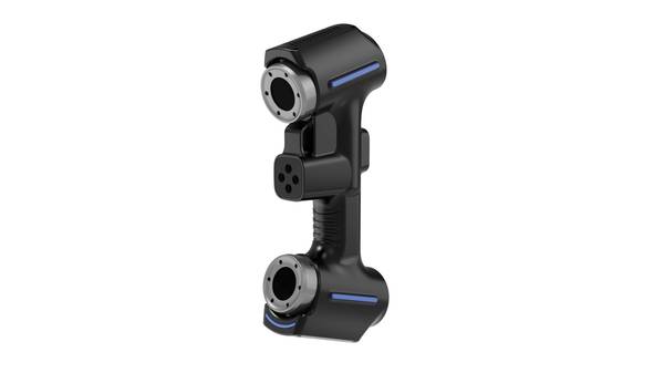
3d scanning automotive: Definition of 3D Scanning for Automotive Applications Definition of 3D Scanning for Automotive Applications 3D scanning in automotive.
Definition of 3D Scanning for Automotive Applications
3D scanning in automotive manufacturing is a non-contact dimensional measurement method. It captures precise 3D geometric data of components and assemblies using structured light or laser projection. Unlike traditional touch-probe CMMs, the scanner records millions of surface points without physically contacting the part.
This makes it suitable for complex freeform surfaces, thin-walled stampings, and soft materials that deflect under probe pressure.
Key Points at a Glance
- 3D scanning in automotive manufacturing is a non-contact dimensional measurement method.
- Laser-based 3D scanning operates on the principle of structured light triangulation.
- Automotive components present three measurement challenges that align directly with laser scanning’s capabilities:
- The conversion from raw scan data to usable engineering output follows a defined sequence:
Within Western manufacturing, the technology fits directly into Industry 4.0 smart factory initiatives. Scan data feeds digital twin workflows, closed-loop quality systems, and automated dimensional reporting. For lean manufacturing, the benefit is straightforward: faster first-article inspection, less scrap from undetected drift, and reduced rework.
A scanner can verify a stamped panel against CAD nominal in minutes rather than hours.
The technology serves three primary cross-functional groups:
| Team | Typical Use |
|---|---|
| Design Engineering | Reverse engineering, prototype validation, CAD comparison |
| Quality Assurance | First-article inspection, GD&T verification, PPAP documentation |
| Production Operations | Tooling wear monitoring, inline spot checks, assembly alignment |
OEMs and tier 1–2 suppliers deploy the same scanning data differently depending on workflow. An engineer uses it to close the loop between design intent and as-built condition. A quality manager uses it for traceable dimensional records. Production uses it to catch process drift before it produces nonconforming parts. The common thread is objective geometric truth, captured quickly and repeatably.
Core Working Principles of Laser-Based 3D Scanning in Automotive Settings
Laser-based 3D scanning operates on the principle of structured light triangulation. A scanner projects one or more laser lines onto a surface. As the line strikes the object, it deforms according to the surface topography. One or more cameras mounted at a known angle to the projector record this deformation.
The system calculates the distance to each point along the line by measuring the angular displacement between the projected line and its observed position on the camera sensor. This is the same geometric reasoning used in optical comparator work, extended across thousands of points per frame.
The raw output of this process is a high-density point cloud. Each point carries X, Y, and Z coordinates in the scanner’s local reference frame. Software then converts this cloud into a triangulated mesh — a continuous digital surface made of small polygonal facets.
For automotive engineering workflows, the mesh can be further processed into CAD-compatible formats such as STEP or IGES, though reverse engineering to a fully parametric solid model often requires additional surfacing work.
Why Laser Scanning Fits Automotive Applications
Automotive components present three measurement challenges that align directly with laser scanning’s capabilities:
| Challenge | Laser Scanning Response |
|---|---|
| Complex curved surfaces (fenders, door skins, intake manifolds) | Non-contact capture follows freeform geometry without fixed-point probing |
| Mixed material assemblies (steel brackets, plastic fascias, carbon-fiber panels) | Surface reflectivity and color variations are handled through exposure control and blue laser technology |
| Tight tolerance verification against GD&T callouts | Dense point spacing allows comparison to nominal CAD across the entire surface, not just discrete points |
The density of the point cloud matters in automotive work. A coordinate measuring machine (CMM) might capture 50 points on a stamped panel. A laser scanner captures millions. That density reveals subtle springback after forming, localized thinning, or weld distortion that sparse probing would miss entirely.
For first-article inspection on injection-molded interior components, the scanner’s ability to capture sink marks, parting line flash, and surface waviness in a single dataset shortens the feedback loop to the tooling shop.
Data Processing Workflow
The conversion from raw scan data to usable engineering output follows a defined sequence:
- Scan acquisition — multiple passes from different orientations capture all visible surfaces
- Point cloud registration — overlapping scans are aligned using reference targets or surface geometry
- Noise filtering — stray points from reflective edges or dust are removed
- Mesh generation — the cleaned cloud is triangulated into a watertight or near-watertight surface
5.
Step five is where the value concentrates for quality engineers. The deviation map provides a visual and quantitative record of where a part deviates from design intent. Tolerance bands can be applied to distinguish acceptable variation from actionable defects.
Limitations and Practical Boundaries
Laser scanning is not a universal solution. Deep internal features — narrow bores, blind holes, undercuts — often require single-line scanning modes with reduced speed. Highly reflective surfaces such as polished chrome or machined aluminum may require matting spray to reduce specular reflection.
Transparent or translucent materials (certain plastics, glass) scatter the laser unpredictably and generally cannot be scanned without surface preparation.
These limitations do not diminish the technology’s role. They define its application envelope. Automotive metrology teams typically deploy laser scanning alongside traditional tactile methods, using each where it performs best. The scanner handles surface geometry and freeform comparison; the CMM verifies critical hole positions and datum features.
This division of labor reflects practical engineering judgment rather than any inherent superiority of one method over the other.
INSVISION, as a manufacturer of industrial 3D scanning equipment, builds systems that apply these fundamental principles across a range of automotive use cases. The underlying physics of laser triangulation remains consistent regardless of implementation specifics.
Key Performance Parameters for Automotive 3D Scanning Solutions
Evaluating a 3D scanning system for automotive use requires a shift away from generic resolution claims. Instead, the practical fit is determined by a set of distinct performance parameters that dictate how the hardware behaves in a production or quality lab environment. These parameters are not marketing metrics;
they are the technical specifications that directly influence cycle time, measurement uncertainty, and the ability to conform to established metrology standards like ISO 10360 and ASME GD&T callouts.
The table below breaks down the critical definitions and their direct impact on automotive workflows. Understanding these distinctions helps engineers align the tool’s capabilities with specific inspection tasks, whether that involves checking a large Class A surface or verifying a tight-tolerance bore on a powertrain component.
| Parameter | Definition | Relevance for Automotive Applications |
|---|---|---|
| Scanning Area | The maximum surface area a 3D scanning system can capture in a single scan pass | Reduces total scan time for large components such as door panels, chassis subframes, and full bumper assemblies, supporting efficient batch inspection workflows |
| Precision Scanning Capability | A high-detail capture mode using multiple parallel laser lines to resolve fine surface features | Enables tight-tolerance dimensional measurement aligned with ISO 10360 and ASME GD&T standards for safety-critical components like brake calipers and powertrain parts |
| Deep Hole Scanning Capability | A specialized mode using a single laser line to access and measure narrow, internal cavities | Supports inspection of engine block bores, fuel injector components, and other hard-to-reach internal features common in automotive powertrain systems |
| High-Speed Scanning Functionality | A rapid capture mode using a high volume of laser lines to scan surfaces at accelerated rates | Enables near-inline quality control for high-volume automotive production lines, aligning with lean manufacturing goals of reduced cycle time |
| Intelligent Feature Recognition | Automated identification of part features such as holes and cut edges during the scanning process | Streamlines inspection of stamped metal parts and composite panels with pre-cut mounting points, reducing post-processing time for quality teams |
From a metrology perspective, these parameters must be evaluated in context. A system with a large scanning area but poor precision mode is useless for a first-article inspection on a brake caliper. Conversely, a high-resolution scanner with a tiny field of view will bottleneck a line trying to audit full fascia assemblies. The goal is to match the hardware behavior to the tolerance stack and the surface geometry.
For instance, deep hole scanning is non-negotiable for cylinder head ports, while high-speed functionality matters more for body-in-white checks where runout tolerance is less strict but throughput is critical.
Solutions like those developed by INSVISION are often assessed against these specific operational criteria rather than a simple “best” ranking, ensuring the hardware fits the engineering constraint rather than forcing the process to adapt to the tool.
Valid Use Boundaries for 3D Scanning in Automotive Operations
The term “valid use boundary” in automotive metrology does not describe a limitation of hardware capability. It defines the operational envelope where a measurement method produces repeatable, auditable data that aligns with engineering tolerances and quality system requirements.
For 3D scanning, this boundary is set by the intersection of part geometry, surface finish, required uncertainty, and the specific deliverable in the product lifecycle. Scanning is not a universal replacement for tactile CMM probing on every feature, but its valid application range in automotive operations is far broader than often assumed.
Use cases cluster around tasks where dense surface data, speed, or access to complex freeform geometry outweigh the need for single-point traceability on simple prismatic features. The table below maps the primary validated use boundaries across the automotive lifecycle, framed by the deliverables each application supports.
| Automotive Application | Primary Deliverable | Why 3D Scanning Fits the Use Boundary |
|---|---|---|
| Reverse engineering of legacy components | CAD model for aftermarket support | Captures freeform surfaces and worn geometry without existing drawings; supports remanufacturing and service part tooling. |
| First article inspection (FAI) for PPAP | Dimensional layout report | Dense point clouds enable full-surface comparison to CAD with GD&T callouts; supports AIAG-aligned submission packages where surface profile and hole position matter. |
| Tool and die verification | Wear analysis and correction data | Scans of stamping dies and injection molds identify springback, draw-in, and wear zones before parts drift out of tolerance. |
| Assembly gap and flush analysis | Build quality metrics | Non-contact scanning of mounted panels and trim produces gap/flush maps across entire closure lines faster than manual gauges. |
| Commercial vehicle MRO inspection | Serviceability assessment | Identifies distortion, corrosion loss, and crack indicators on frames, brackets, and structural members without disassembly. |
| Composite part validation for EV | Ply orientation and thickness mapping | Blue laser scanning captures thin-walled composite battery enclosures and aerodynamic components; validates as-built vs. as-designed surfaces. |
Alignment with AIAG quality guidelines matters here. PPAP and APQP processes in Western markets require measurement systems that demonstrate gage R&R stability, correlation to master data, and documented uncertainty. A 3D scanning workflow fits within that framework when the system is validated for the specific feature class being reported.
For example, scanning a stamped body panel for surface profile is a well-established practice. Scanning a bearing bore with a 5 µm diameter tolerance is not — that remains a tactile CMM or bore gage task. The boundary is not about the scanner; it is about whether the measurement uncertainty of the full scanning process is small enough relative to the tolerance band.
A second boundary condition involves surface preparation. Automotive parts with glossy, transparent, or highly reflective finishes — polished shafts, chrome trim, clear plastic lenses — can require developer spray or matting agents. That step changes throughput and must be accounted for in cycle time planning.
Deep hole scanning modes using a single blue laser line, such as those available on certain INSVISION systems, extend the valid boundary into recessed features like threaded inserts and connector pockets, where multi-line scan patterns lose data density. Hole rescanning that intelligently identifies cut edges further pushes the practical boundary toward features previously reserved for touch probing.
The most common misuse of 3D scanning in automotive operations is not scanning too much. It is scanning without a defined acceptance protocol. A valid use boundary includes a documented correlation study, a known alignment method, and a clear statement of which GD&T callouts the scan report can and cannot support. When those conditions are met, the boundary expands across nearly every non-prismatic surface in the vehicle.
When they are absent, even a flat plate scan can be argued as invalid.
Common Misconceptions About Automotive 3D Scanning
Despite the maturity of optical metrology, several misconceptions persist regarding 3D scanning automotive components. These beliefs often stem from experiences with older generation equipment or a misunderstanding of current calibration standards.
Misconception 1: 3D scanning lacks the accuracy for safety-critical parts.
This is perhaps the most common objection raised in quality departments. The assumption is that tactile CMMs are inherently superior for tight tolerances. In practice, modern calibrated laser systems are routinely used for first-article inspection (FAI) of body-in-white assemblies and powertrain components.
When operated in accordance with ISO 10360 guidelines, these systems can validate GD&T callouts and surface profiles within tolerances that were previously exclusive to touch probing. The key distinction is not the technology itself, but the verification of accuracy against traceable standards.
Misconception 2: Every surface requires heavy preparation.
Many engineers assume that reflective metal or transparent materials must be coated with a matting spray before scanning. While this was true for older white-light scanners, advanced blue laser technology is less sensitive to ambient light and surface reflectivity. Systems can frequently capture data directly from machined aluminum, stamped steel, and carbon fiber weave without developer spray.
Preparation is now the exception, not the rule.
Misconception 3: Scanning is too slow for volume production.
There is a lingering belief that 3D scanning is a laboratory technique, unsuitable for the line speed of automotive manufacturing. However, high-speed scanning modes have shifted the bottleneck. Near-inline inspection is achievable when the scan time is shorter than the upstream process cycle time.
| Workflow Attribute | Traditional CMM Check | Modern 3D Scanning |
|---|---|---|
| Data Density | Sparse point collection | Full surface deviation map |
| Part Handling | Rigid fixturing required | Flexible alignment options |
| Surface Prep | Not required | Minimal or none for most substrates |
| Throughput | Slower for complex geometry | Faster for dense feature capture |
The remaining constraint is rarely the scanner speed. It is the part handling workflow and the automation of data processing. When paired with standardized fixtures and automated reporting, high-speed scanners keep pace with high-throughput lines. INSVISION solutions, for example, are designed to integrate into these standardized industrial workflows without requiring proprietary workarounds.
Related Concepts in Automotive Dimensional Quality Management
Dimensional quality in automotive manufacturing does not operate in isolation. A 3D scanning system delivers point-cloud data, but that data only becomes actionable when it connects to established engineering and quality frameworks. Several adjacent concepts determine how scanning results are interpreted, approved, and integrated into production workflows.
Geometric Dimensioning and Tolerancing (GD&T) is the language used to define allowable variation on part features. Standards such as ASME Y14.5 and ISO 1101 specify how datums, position tolerances, and profile callouts are applied. 3D scanning data is typically compared against these GD&T callouts within inspection software, converting raw measured geometry into pass/fail or deviation reports.
Without a clear GD&T scheme, scan data lacks a standardized interpretation basis.
Production Part Approval Process (PPAP) governs how suppliers demonstrate that production parts meet dimensional requirements before serial delivery. AIAG-aligned PPAP submissions often include dimensional layout reports, which 3D scanning supports by capturing full-surface measurements faster than traditional point-based methods. The scan data feeds directly into the dimensional results section of the PPAP package.
Coordinate measuring machines (CMMs) remain the reference method for many automotive dimensional checks. CMMs capture discrete points with high accuracy but are slower for full-surface characterization. 3D scanning complements CMM workflows by covering large areas quickly, while CMMs validate critical features or serve as arbitration tools when scan results are disputed.
Digital twin integration connects scan data to the nominal CAD model throughout product development and production. As-built scan geometry can be aligned to the CAD reference, creating a living digital representation used for root-cause analysis, tooling correction, and virtual assembly studies. This closes the loop between design intent and physical reality.
Industry 4.0 smart quality systems require measurement data to flow into broader manufacturing execution and quality management platforms. 3D scanning outputs, when structured properly, feed statistical process control dashboards and traceability databases, enabling real-time dimensional monitoring rather than end-of-line batch inspection.
| Concept | Primary Role | How 3D Scanning Data Integrates |
|---|---|---|
| GD&T (ASME Y14.5 / ISO 1101) | Defines tolerances and datums | Scan data compared against callouts in inspection software |
| PPAP (AIAG) | Supplier part approval | Dimensional layout reports generated from scan data |
| CMM | Discrete-point reference measurement | Validates scan results; used for critical features |
| Digital Twin | CAD-to-physical alignment | Scan geometry aligned to nominal model for analysis |
| Industry 4.0 Quality | Real-time process control | Scan outputs feed SPC and traceability systems |
The practical outcome is that automotive teams do not replace existing quality infrastructure with 3D scanning. They extend it. Scan data becomes most valuable when it plugs into the same GD&T, PPAP, and digital twin frameworks already governing supplier and production operations.
INSVISION scanning hardware and software are designed to output data compatible with these standardized workflows, rather than creating a parallel measurement silo.
Role of Specialized 3D Scanning Technology Providers in Automotive
Specialized 3D scanning providers serve a different function than general-purpose metrology vendors. Instead of adapting off-the-shelf hardware to automotive work, these developers design optical measurement systems around the specific constraints automotive engineers face daily: reflective machined surfaces, deep stamping cavities, large body panels, and tight GD&T callouts that must be verified without moving parts to a dedicated lab.
The practical value shows up in three recurring applications. Quality control teams use laser-based scanning to capture full surface geometry and compare it against CAD nominals, catching springback in stamped panels or weld distortion before parts reach assembly. Reverse engineering groups rely on the same data to reconstruct legacy tooling or benchmark competitor components where drawings no longer exist.
Tooling verification rounds out the workload—checking die wear, fixture alignment, and locating-pin positions against design intent.
What separates specialized providers is how they handle measurement standards. Western OEM and tier supplier facilities operate under ISO and ASME frameworks, which means scan data must align with established GD&T evaluation methods, not proprietary reporting formats.
A provider that understands datum structures, profile tolerances, and first-article inspection workflows reduces the friction of introducing optical measurement into an existing quality system.
INSVISION fits within this category as a developer of laser-based 3D scanning solutions for automotive use cases such as quality control, reverse engineering, and tooling verification. Their systems are built around the measurement demands outlined above, with an emphasis on alignment to global industrial standards rather than closed, single-vendor workflows.
The table below summarizes how specialized scanning criteria map to common automotive inspection needs:
| Automotive Requirement | Scanning System Criterion | Why It Matters for Quality Teams |
|---|---|---|
| Panel and large-part inspection | Scanning area up to 650mm × 550mm per capture | Reduces setup time; fewer scans to cover a hood or door assembly |
| Deep hole and cavity measurement | Single blue laser line mode | Reaches into stamping cavities and machined bores where multi-line patterns fail |
| High-throughput surface capture | Multiple parallel blue laser lines | Speeds up full-body scans without sacrificing point density |
| GD&T conformance reporting | Standards-aligned evaluation workflow | Supports ISO/ASME compliance for Western OEM and tier facilities |
One common misconception is that a higher laser line count always produces better results. In automotive work, a single-line mode often outperforms multi-line configurations on dark or reflective surfaces, deep recesses, and sharp edge transitions. The scanning mode should match the feature geometry, not the marketing spec sheet.
For engineering teams evaluating specialized providers, the relevant criteria are straightforward: scanning area coverage, availability of a single-line deep-hole mode, data density in precision scanning, and whether the software output integrates with existing CMM and CAD platforms.
A provider that understands these criteria and builds hardware around them offers more practical value than one that treats automotive as just another vertical market.
Frequently Asked Questions About 3D Scanning for Automotive
What types of automotive components can be measured with 3D scanning?
The practical range is broader than many engineers first assume. Non-contact optical measurement works across most rigid components where surface geometry matters. That includes body panels, door apertures, stamped brackets, cast suspension knuckles, molded interior trim, and complete welded subassemblies. The limiting factors are usually line-of-sight access and surface finish.
Deep bores and narrow channels require specific scanning strategies, such as a single laser line mode, to capture data where wider multi-line patterns cannot reach. Transparent or highly reflective surfaces may need a temporary matting spray, a standard practice in the industry, before data acquisition.
How does 3D scanning support compliance with automotive quality standards?
Quality standards such as IATF 16949 and customer-specific requirements from OEMs depend on documented measurement data, not subjective judgment. 3D scanning supports this in two direct ways. First, it generates dense point clouds that allow dimensional evaluation against CAD nominals, including GD&T callouts for profile, position, and flushness. Second, the digital record is repeatable and archivable.
An inspector can compare a scan taken during first-article inspection with a scan taken after tooling adjustment or production ramp-up. The data supports PPAP documentation and ongoing process capability studies without relying on hard gauges that may not capture freeform surface deviation.
Can 3D scanning data integrate with existing automotive CAD and quality software?
Yes, provided the workflow is built around neutral file formats. Raw scan data is typically exported as mesh geometry in STL, OBJ, or PLY formats. For dimensional inspection, software commonly generates point-to-CAD comparisons using the original NX, CATIA, or SolidWorks model as reference.
The critical step is alignment: a best-fit or datum-based alignment must match the engineering coordinate system before any deviation analysis has meaning. Quality engineers then work with color maps, cross-section reports, and exported CSV or PDF results. Integration is not automatic; it requires defined templates and a clear understanding of which reference system the CAD model uses.
Is 3D scanning suitable for both low-volume custom vehicle production and high-volume mass manufacturing?
The technology serves both, but the implementation logic differs. In low-volume or prototype work, scanning replaces many hard gauges and manual layout inspections. The ability to scan a one-off part, compare it to CAD, and iterate within hours is valuable when tooling costs must stay low. In high-volume production, scanning is rarely used for 100% inline inspection due to cycle-time constraints.
Instead, it supports offline measurements, dimensional audits, and root-cause analysis for specific failures. The table below summarizes typical application fits.
| Production Context | Typical Role for 3D Scanning | Common Deliverable |
|---|---|---|
| Prototype / custom build | First-article verification, reverse engineering | CAD comparison report, adjusted CAD model |
| Tooling tryout | Die or mold validation before production sign-off | Surface deviation map, section analysis |
| Mass production | Audit inspection, problem solving | Statistical dimensional report, trend data |
| Supplier quality | Incoming part validation against OEM CAD | PPAP dimensional layout, color map report |
The key decision is not whether scanning works, but where in the quality loop it provides the most useful data for the cost and time involved.
Summary of Core 3D Scanning Automotive Fundamentals
For quality engineers and manufacturing planners, the core value of 3D scanning in automotive applications rests on a few non-negotiable fundamentals. The process relies on structured light projection—typically blue laser lines—to capture surface geometry as dense point-cloud data. That data is then meshed into a digital twin for dimensional inspection, reverse engineering, or tooling correction.
The working principle is straightforward: a scanner projects a known pattern onto a part, cameras record the pattern’s deformation, and software triangulates millions of surface points. What separates useful data from noise in an automotive environment is not just resolution, but how the scanner handles variation in surface finish, edge definition, and access to recessed features.
Key performance parameters that determine fit for automotive workflows include scanning area, laser-line configuration, and the ability to switch between precision and high-speed modes. The table below summarizes common mode distinctions and their typical application context.
| Parameter | Typical Configuration | Automotive Use Context |
|---|---|---|
| Precision scanning | 7 blue laser lines | Complex geometry, tight GD&T callouts, first-article inspection |
| High-speed scanning | 26–50 blue laser lines | Large body panels, rapid surface capture, reverse engineering |
| Deep hole scanning | 1 single blue laser line | Threaded bosses, connector recesses, blind holes |
| Scanning area | 650 mm × 550 mm (typical handheld) | Mid-size components, interior trim, cast housings |
| Large-area scanning | Up to 2200 mm × 2200 mm | Full door assemblies, bumper fascias, floor pans |
Standard alignment matters more than raw point density. Automotive metrology programs typically reference ISO 10360 or ASME B89.4.19 for acceptance testing, and scan data must integrate cleanly with CAD-based inspection software. A scanner that cannot hold volumetric accuracy across its stated scanning area will generate misleading deviation maps—regardless of how many laser lines it projects.
Valid use cases cluster around three workflows: dimensional inspection against nominal CAD, reverse engineering of legacy parts without drawings, and tooling verification for stamping dies or injection molds. In each case, the scanner is not a replacement for CMMs or gages; it is a complementary data source that trades point-level accuracy for full-field coverage and speed.
Common misconceptions persist. Faster scanning does not automatically mean better inspection. High-speed modes with 26 or 50 laser lines capture large surfaces quickly, but they may sacrifice edge sharpness or small-feature resolution. Precision modes with fewer lines provide cleaner data on feature-rich areas. The practical approach in automotive work is mode selection based on feature density, not a single default setting.
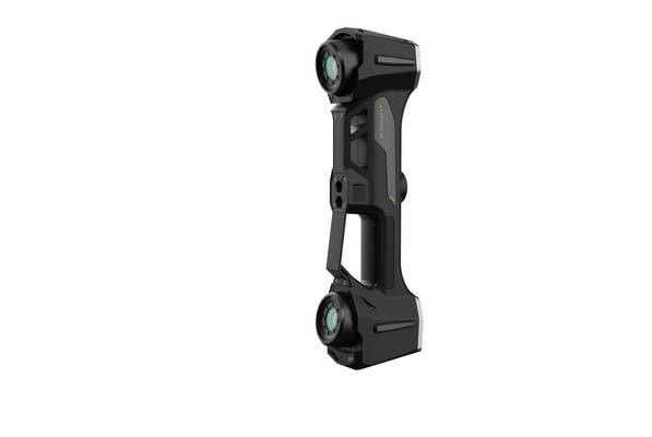
A restrained brand note: INSVISION’s handheld systems illustrate the general category well—offering selectable scanning modes and scan areas up to 650 mm × 550 mm for mid-size automotive components. The underlying principles, however, apply across any structured-light scanner used in an automotive quality or engineering workflow.
- What Is 3D Scanning? Principles, Workflow, and Industrial Applications 3D scanning is a digital measurement technology that converts the surface geometry of physical objects into 3D data. This entry covers its working principles, core parameters, industrial use cases, common misconceptions, and related technical…
- What Is a 3D Scanner? Types, Parameters, and Selection Criteria A 3D scanner captures three-dimensional surface data from physical objects and converts geometry, dimensions, and features into digital data for inspection, reverse engineering, and modeling.
- What Is 3D Scanning Accuracy? Accuracy, Repeatability, and Resolution Explained 3D scanning accuracy describes how closely scan data matches an object's actual geometry and dimensions. It is assessed through local accuracy, volumetric accuracy, stitching accuracy, repeatability, and resolution.
- What Is Point Cloud Data? Point Clouds, Meshes, and CAD Models in 3D Scanning Point cloud data is an important raw data format in 3D scanning. It consists of discrete 3D coordinate points that describe object surface geometry and support inspection, reverse engineering, modeling, and archiving.
Hangzhou Insvision Technology Co., Ltd.
Address: Building 1, No. 1399 Liangmu Road, Yuhang District, Hangzhou, Zhejiang 311121, China
Copyright © Hangzhou Insvision Technology Co., Ltd. All rights reserved.
Copyright © Hangzhou Insvision Technology Co., Ltd. All rights reserved.