

Key Fundamentals of 3D Scanning Structured Light Technology for Industrial Applications
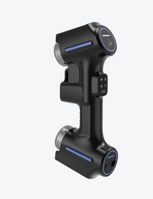
The result is full-field geometric data: millions of X, Y, Z coordinates captured in seconds, rather than discrete touch points collected one at a time.
Definition of 3D Scanning Structured Light
Definition of 3D Scanning Structured Light
Structured light 3D scanning is a non-contact, non-destructive optical measurement technique that projects a known light pattern—typically a series of parallel fringes, grids, or coded binary patterns—onto a physical object and reconstructs its three-dimensional surface geometry from the observed deformation of that pattern.
One or more calibrated cameras record how the projected pattern distorts across the object’s contours, and triangulation algorithms convert those distortions into dense point clouds. The result is full-field geometric data: millions of X, Y, Z coordinates captured in seconds, rather than discrete touch points collected one at a time.
Unlike coordinate measuring machines (CMMs), which rely on physical probes making contact with the surface, structured light scanners acquire data without applying force to the part. That distinction matters in industrial metrology.
Thin-walled components, elastomer seals, composite panels, and freshly machined surfaces can deform or deflect under even light probe pressure, introducing measurement uncertainty that structured light avoids entirely. The technology also captures freeform and organic shapes—turbine blade airfoils, stamped sheet metal, cast housings—at resolutions impractical for point-by-point probing.
Within Western manufacturing environments, structured light scanning fits naturally into lean manufacturing and Industry 4.0 frameworks. First-article inspection workflows that once required hours of CMM programming can be supplemented with rapid full-surface acquisition, feeding GD&T evaluation software against the same ASME Y14.5 callouts used in traditional layouts.
The data format—dense, digital, and repeatable—supports statistical process control, digital twin construction, and archivable inspection records aligned with ISO 9001 and AS9100 documentation expectations. Structured light is not a replacement for contact metrology in every case; CMMs retain advantages for deep bores, highly reflective untreated surfaces, and traceability chains requiring tactile verification.
But for surface geometry, comparative analysis, and reverse engineering, structured light has become a standard tool in the modern quality lab.
The table below summarizes the foundational distinction between the two measurement approaches:
| Criterion | Structured Light 3D Scanning | Contact CMM |
|---|---|---|
| Data acquisition | Full-field, millions of points per scan | Discrete point-by-point probing |
| Surface contact | None (non-destructive) | Physical probe contact |
| Part deformation risk | None from measurement force | Possible on soft or thin materials |
| Freeform surface capture | Native strength | Requires dense point programming |
| Deep internal feature access | Limited by line-of-sight | Strong with appropriate probe configurations |
| Typical industrial fit | Surface inspection, reverse engineering, digital archiving | Geometric dimensioning of prismatic features, high-precision bore checks |
INSVISION operates within this structured light segment, supplying systems that address the practical constraints of production-floor metrology rather than laboratory-only applications. The definition above establishes the technical foundation relevant to any structured light system, regardless of vendor.
Core Working Principles of Structured Light 3D Scanning
Structured light 3D scanning operates on the principle of active optical triangulation. Unlike passive photogrammetry, which relies on ambient lighting and surface texture, structured light systems project a known pattern onto a target. This pattern is distorted by the object’s topography. By analyzing these distortions, the system reconstructs surface geometry with high precision.
The operational sequence follows four stages.
- Pattern Projection
A digital projector emits a sequence of predefined light patterns. Common configurations include sinusoidal fringe patterns, binary grid structures, or stochastic speckle patterns. Fringe projection is the most widely used for metrology-grade work. The projector cycles through multiple phase-shifted patterns to eliminate ambiguity and improve resolution.
- Image Capture
One or more calibrated cameras record the deformed patterns as they fall across the object’s surface. Stereo camera arrays are standard in industrial systems; multi-camera setups extend coverage and reduce occlusions. The cameras capture at fixed angles relative to the projector, establishing a known geometric baseline.
- Triangulation and Phase Decoding
For every camera pixel, the system compares the observed pattern against the projected reference. The local phase shift maps directly to height variation. Triangulation algorithms then calculate 3D coordinates for each pixel. The result is a dense set of X, Y, Z data points.
- Point Cloud and Mesh Generation
The coordinate data is compiled into a high-density point cloud. Post-processing software converts this into a polygon mesh, often with texture mapping. Downstream applications include dimensional inspection, reverse engineering, and CAD comparison.
| Stage | Input | Process | Output |
|---|---|---|---|
| Projection | Digital pattern file | Phase-shifted or binary pattern emission | Illuminated target surface |
| Capture | Distorted pattern reflections | Stereo or multi-camera imaging | Raw image pairs |
| Triangulation | Image pairs + calibration data | Phase decoding, disparity mapping | 3D coordinate cloud |
| Post-processing | Point cloud | Meshing, hole filling, decimation | Watertight polygon model |
System Calibration and Traceability
Calibration is not a one-time setup step. It defines the geometric relationship between projector and cameras, lens distortion parameters, and the scale reference. Industrial structured light scanners are typically calibrated using certified artifacts — such as ball bars or gauge blocks — traceable to national metrology institutes.
This traceability chain allows measurement results to be reported against standards like ISO 10360 or VDI/VDE 2634.
INSVISION structured light systems include calibration routines designed to maintain this traceability in production environments. The calibration model compensates for thermal drift and mechanical shifts, ensuring that repeated measurements remain within stated uncertainty budgets.
A common misconception is that higher camera resolution automatically yields better accuracy. Resolution contributes, but triangulation geometry, pattern quality, and calibration stability often matter more. Engineers evaluating systems for first-article inspection or GD&T verification should examine the full measurement chain, not the sensor specification alone.
Key Performance Parameters for Industrial Structured Light 3D Scanning
Evaluating a structured light 3D scanning system for industrial use requires moving past datasheet headlines. The practical value of a scanner depends on how its core parameters interact with specific measurement tasks, tolerances, and production environments. Six metrics consistently drive engineering decisions in this segment.
Measurement accuracy is the degree of agreement between a scanned result and a calibrated reference standard, typically expressed as a volumetric length error or single-point sigma. For automotive OEM dimensional inspection, this parameter directly determines whether a stamped panel or welded assembly can be validated against GD&T callouts without adding manual CMM checks.
Point density describes the spatial resolution of acquired 3D data—how many measurement points fall within a given surface area. Aerospace MRO composite part assessment depends on point density to resolve small impact damage, delamination bulges, or fastener hole deformation that coarser systems would smooth over.
Scan volume defines the three-dimensional field of view captured in a single setup. Larger volumes reduce the number of registrations required for a complete part, but often at the cost of resolution. Medical device conformity verification tends to favor smaller, high-detail scan volumes for implants and surgical guides, while energy component quality control may prioritize larger volumes for turbine housings or pipe fittings.
| Parameter Category | Formal Definition | Industrial Application Relevance |
|---|---|---|
| Measurement accuracy | Deviation between measured 3D coordinates and traceable reference values, commonly stated as a length-dependent error band | Determines whether a scanner can replace tactile inspection for automotive stamped parts, castings, or machined features with tight GD&T tolerances |
| Point density | Number of acquired 3D points per unit area or per scan line, defining spatial sampling resolution | Controls ability to detect small surface anomalies—aerospace composite defects, medical implant surface finish deviations, or fine weld geometry |
| Scan volume | The measurable 3D region captured in one acquisition cycle without moving the scanner or part | Balances throughput against detail; large energy components need wide volumes, while small medical devices benefit from narrow, high-resolution fields |
| Single-shot acquisition speed | Time required to capture one complete 3D frame or pattern sequence | Affects line-side inspection feasibility in automotive production and reduces motion-induced error when scanning large aerospace structures |
| Working distance range | The span of standoff distances at which the scanner maintains specified accuracy and resolution | Defines accessibility in confined assemblies, weld cells, or MRO hangar environments where scanner placement is physically constrained |
| Ambient light compatibility | Tolerance for external illumination during data acquisition without loss of data quality or measurement repeatability | Determines whether scanning can occur on a factory floor near windows, in outdoor energy sites, or under bright shop lighting without controlled enclosures |
Working distance range matters more in practice than many buyers anticipate. Structured light scanners project patterns and image them from a known baseline. If the standoff distance shifts outside the calibrated range, triangulation geometry degrades. Aerospace MRO work frequently involves scanning installed components or wing sections where physical access restricts the scanner to awkward distances.
Energy component quality control faces similar constraints around pipe runs and valve assemblies.
Single-shot acquisition speed is not just about cycle time. Faster capture reduces sensitivity to vibration and part movement, which becomes critical in automotive OEM settings where line-side inspection may occur without a dedicated measurement cell. Structured light systems that acquire a full frame in milliseconds can tolerate more production-floor motion than slower multi-shot approaches.
Ambient light compatibility separates laboratory instruments from industrial tools. Structured light scanners rely on projected patterns at specific wavelengths. Strong sunlight or certain factory lighting can wash out these patterns if the system lacks sufficient optical filtering or high-intensity projection.
Western manufacturing environments increasingly demand scanning at the point of production rather than in metrology labs, making this parameter a practical gate for adoption.
These parameters do not exist in isolation. A scanner with excellent accuracy but poor ambient light tolerance may be unusable in a plant with skylights. High point density means little if the scan volume forces excessive stitching that accumulates registration error.
Engineers evaluating systems for automotive, aerospace, medical, or energy applications should weigh each metric against the specific surface types, tolerances, and environmental conditions they face. INSVISION structured light systems are engineered with these trade-offs in mind, balancing resolution, speed, and environmental robustness for industrial measurement tasks rather than optimizing a single headline number.
Optimal Use Boundaries for Industrial Structured Light 3D Scanning
Structured light 3D scanning operates on a triangulation principle: a projector casts a known fringe pattern onto a surface, one or more cameras record the pattern deformation, and software reconstructs the three-dimensional geometry from that deviation. The method is inherently fast and dense, but its reliability window is defined by specific physical and environmental constraints.
Understanding those boundaries matters more than chasing maximum point counts.
Ideal Target Object Characteristics
The strongest results come from parts that stay rigid during capture. Structured light systems capture full-field data in fractions of a second, yet any movement between projector pulses and camera exposure degrades data quality. Rigid castings, machined housings, injection-molded covers, and welded assemblies are good candidates.
Components with thin walls, unsupported overhangs, or vibration-prone structures require fixturing or damping.
Surface finish is the second major variable. Matte to semi-gloss finishes scatter the projected pattern predictably, producing clean phase maps. Polished metals, mirror-like surfaces, and translucent materials defeat the method unless developers apply a temporary matting spray. Surface coatings alter measured geometry slightly;
teams performing tight GD&T inspections should account for coating thickness in their uncertainty budgets.
| Object Characteristic | Strong Fit | Weak Fit | Practical Notes |
|---|---|---|---|
| Surface finish | Matte, sand-cast, machined with light oil | Mirror-polished, transparent, black | Developer spray helps but adds thickness |
| Part rigidity | Castings, forgings, rigid assemblies | Thin sheet metal, rubber mounts | Fixture or damp vibration sources |
| Size range | 50 mm to 3 m typical | Sub-10 mm fine features | Multiple scans and stitching required beyond frame |
| Color variation | Uniform or moderate contrast | High-contrast painted markings | Exposure bracketing may be needed |
Environmental Conditions
Structured light scanning tolerates typical shop floor conditions better than many contact measurement methods, but it is not immune to ambient interference. Strong overhead lighting, direct sunlight through dock doors, or nearby welding arcs can overwhelm the projector signal. Controlled shop floor settings, metrology labs, and enclosed production line integration environments provide the most repeatable results.
Temperature stability deserves attention. Thermal drift in the scanner housing, the part, or the mounting fixture introduces systematic errors that repeatable but wrong measurements can mask. Allowing parts and equipment to reach thermal equilibrium before scanning reduces this risk. For production line integration, mounting the scanner on a rigid frame isolated from conveyor vibration keeps calibration stable across shifts.
High-Impact Use Cases
Three application families consistently benefit from structured light scanning when applied within the boundaries above.
Quality control and first-article inspection leverage the dense point cloud to compare as-built geometry against CAD nominal data. Color map deviation plots highlight form errors, weld distortion, and machining mismatch quickly. Teams working to ASME Y14.5 or ISO GPS standards can extract GD&T callouts such as surface profile, flatness, and positional tolerances from the scan data.
The method does not replace CMM verification for every feature, but it reduces the number of features requiring tactile probing.
Reverse engineering workflows benefit from the full-field capture of organic and freeform surfaces that are impractical to define with hand tools. Scanned mesh data feeds into CAD reconstruction for legacy parts with no existing drawings. The density of structured light data captures subtle curvature changes that sparse probing misses.
Digital twin development requires accurate as-built geometry, not just nominal CAD. Structured light scanning provides the dimensional backbone for virtual commissioning, finite element meshing, and wear monitoring over time. The same scan data can serve multiple downstream uses without re-measuring the part.
Fit-for-Purpose Assessment
Structured light scanning is not a universal replacement for all dimensional measurement. It adds the most value when parts have freeform complexity, when dense surface data supports GD&T evaluation, or when a digital record of as-built geometry carries downstream value. It adds less value when measuring deep internal bores, threaded holes, or features hidden from line of sight.
Teams evaluating the method should define measurement requirements first, then confirm that target parts, surface conditions, and operating environment fall within the boundaries described here. Systems such as those offered by INSVISION are designed around these application boundaries, with hardware and software tuned for the industrial conditions where structured light delivers repeatable, high-precision results.
Common Misconceptions About Structured Light 3D Scanning
Structured light 3D scanning projects a known pattern sequence onto a surface and reconstructs geometry from the observed deformation of that pattern. The measurement principle itself is well documented. Yet several assumptions about its practical limits persist in manufacturing environments, often shaping purchase decisions before a formal evaluation ever takes place. Three of these assumptions deserve direct correction.
Misconception 1: Reflective Surfaces Cannot Be Scanned
The belief that structured light scanning fails on shiny or polished metal surfaces stems from early-generation systems and low-cost consumer-grade hardware. Those devices struggled when projected patterns reflected away from the camera or produced specular highlights that saturated the sensor. Modern industrial systems address this differently.
Industrial-grade projection tuning adjusts exposure, pattern intensity, and fringe contrast dynamically during measurement. Some systems combine multiple exposures per scan position, merging data from bright-field and dark-field captures to recover geometry from surfaces that would otherwise return inconsistent data. This is not post-processing trickery; it is a deliberate sensor design strategy.
Where surfaces remain problematic—mirror-finished tooling, chrome-plated components, or polished turbine blades—optional surface preparation aids offer a practical route. Spray developers, matting powders, or removable coatings create a temporary diffuse layer that returns clean fringe data without altering the part’s critical dimensions.
The key point is context: reflective surfaces require the right projection strategy or preparation protocol, not a different measurement technology by default.
Misconception 2: Structured Light Only Works for Small Precision Parts
Early structured light systems were marketed heavily toward dental labs, electronics inspection, and small precision components. That history created a lingering assumption that the technology tops out at parts measured in centimeters.
Scalable system configurations change this picture. Structured light scanners are available with fields of view ranging from a few millimeters to over a meter, depending on the projector optics, camera configuration, and standoff distance. A medical implant manufacturer and an aerospace MRO team may use the same underlying measurement principle with entirely different hardware configurations.
The table below outlines typical application envelopes:
| Component Class | Approximate Size Range | Typical Structured Light Configuration |
|---|---|---|
| Medical implants, connectors | 5–100 mm | Small field of view, high-resolution cameras |
| Automotive brackets, housings | 100–500 mm | Mid-range FOV, automated turntable or robot cell |
| Aerospace subassemblies, composite panels | 0.5–3 m | Large FOV, multi-camera rig or tracked scanning |
Large-area scanning does introduce trade-offs in resolution and accuracy per unit length. A system configured for a 2-meter panel will not resolve the same fine detail as one set up for a 20-mm connector. That is a configuration constraint, not a technology ceiling.
Misconception 3: Operation Requires Extensive Specialized Training
The assumption that structured light scanning demands a dedicated metrology specialist persists in organizations that have not revisited the technology in several years. Older systems did require careful calibration routines, manual point-cloud cleanup, and deep familiarity with inspection software.
Current industrial platforms reflect a different design philosophy. Calibration is often guided or automated, with the scanner validating its own alignment against reference artifacts. Measurement workflows follow step-by-step templates that a quality technician can learn in days rather than weeks. The software handles mesh generation, hole filling, and alignment to CAD nominals without manual intervention in most cases.
This matters for lean manufacturing teams. If a scanning station requires a full-time expert, it becomes a bottleneck. If a trained operator can run first-article inspection alongside existing CMM duties, the technology integrates into the quality workflow rather than disrupting it.
Manufacturers evaluating structured light systems should ask vendors directly about operator training time, workflow automation, and how the system handles GD&T callouts and dimensional reporting—not assume that complexity is inherent to the method.
INSVISION has addressed these workflow considerations in its structured light scanning platforms, with a focus on reducing operator dependency in production inspection environments. The engineering principle remains consistent: structured light scanning is a measurement method whose practical limits depend on system design, configuration, and workflow integration—not on the technology category itself.
Related 3D Measurement Technologies and Core Distinctions
Non-contact 3D measurement spans several distinct physical principles. The choice between them is not about which is superior, but which matches the surface condition, standoff distance, and tolerance requirement of a given inspection task.
Structured light scanning is one member of this family, and it is most useful when a dense point cloud, moderate working distance, and fast full-field acquisition matter more than extreme range or direct sunlight tolerance.
Laser Triangulation Scanning
Laser triangulation projects a single line or point onto a surface and observes its deformation from a known offset angle. The scanner reconstructs geometry from the observed displacement. This approach works well on shiny or dark surfaces that can confuse full-field fringe projection systems, and it remains common in automated in-line inspection cells where a part passes under a fixed scanner.
The trade-off is acquisition speed: a line scanner must traverse the surface, so full-field coverage takes longer than a structured light system that captures an entire projected pattern in one exposure.
Time-of-Flight (ToF) Scanning
Time-of-flight scanners measure the round-trip travel time of a laser pulse or modulated signal to determine distance. These systems operate at long standoff distances — meters to hundreds of meters — and are used for large-volume capture such as building interiors, civil infrastructure, or large castings.
Their measurement uncertainty is typically higher than structured light or triangulation systems, but their long-range capability makes them the only practical option for certain large-scale tasks.
Photogrammetry
Photogrammetry derives 3D coordinates from multiple overlapping photographs taken from different positions. It requires no active projection and can scale from small machined parts to entire aircraft assemblies when coded targets are used. Industrial photogrammetry systems often serve as a reference network for other scanners, providing a volumetric accuracy backbone for large-scale alignment.
They capture fewer points per unit area than structured light scanning but offer flexibility in field conditions and very large measurement volumes.
The following table summarizes the functional boundaries between these technologies:
| Technology | Working Distance | Point Density | Primary Strength | Typical Industrial Use |
|---|---|---|---|---|
| Structured light scanning | 0.1–2 m | Very high | Full-field speed, dense data | First-article inspection, reverse engineering, GD&T surface profiling |
| Laser triangulation | 0.05–1 m | High | Surface tolerance on shiny/dark parts | In-line automated inspection, hard-to-scan materials |
| Time-of-flight | 1–300+ m | Low to moderate | Long-range capture | Facilities, infrastructure, large-scale site documentation |
| Photogrammetry | 0.5–100+ m | Low per image | Large-volume reference networks | Aircraft assembly alignment, tooling verification, deformation tracking |
These categories are not mutually exclusive in practice. Some industrial workflows combine photogrammetric reference targets with structured light scanning to maintain volumetric accuracy across a large object. Others pair laser triangulation with a robot cell for high-throughput production inspection where structured light would be too sensitive to ambient conditions.
The key distinction for an engineering audience is this: structured light scanning prioritizes dense, fast, full-field acquisition over a defined working volume. Other methods trade that density for surface robustness, long range, or large-volume scalability.
Selecting the correct technology starts with the measurement task itself — the surface type, required point spacing, environmental conditions, and the tolerance band that must be verified.
INSVISION work in this field has focused on structured light scanning applications for industrial inspection, where dense point clouds and repeatable measurement workflows are central to first-article and production verification processes.
INSVISION’s Contribution to Industrial Structured Light 3D Scanning
Structured light 3D scanning has moved from laboratory curiosity to a standard metrology tool in many Western manufacturing environments. The principle is straightforward: a projector casts a known light pattern onto a surface, one or more cameras record how that pattern deforms, and software reconstructs the geometry by triangulation.
What separates industrial systems from consumer-grade scanners is not the basic physics but the engineering around it — thermal stability of the optical path, calibration traceability, and the ability to hold accuracy across a stated measurement volume.
INSVISION operates in this industrial segment. The company develops structured light systems engineered for high-precision metrology and digital manufacturing workflows, with application focus in automotive, aerospace, medical device, and energy sectors.
Rather than positioning structured light as a general-purpose capture tool, the engineering emphasis falls on repeatability and data quality suitable for dimensional inspection and reverse engineering tasks where GD&T callouts and first-article reporting matter.
The table below outlines typical criteria engineers evaluate when deploying structured light scanning in production or quality contexts:
| Evaluation Criterion | Industrial Relevance |
|---|---|
| Calibration traceability | Links scan data to certified length standards, supporting ISO/ASME inspection documentation |
| Thermal stability | Minimizes drift during longer measurement sessions or on the shop floor |
| Point spacing and resolution | Determines ability to resolve small features, edge radii, and fine surface deviations |
| Data export workflow | Direct transfer of mesh or point cloud data into CAD and metrology software platforms |
| Repeatability under variation | Consistency of results across operators, ambient lighting shifts, and part finish changes |
In practice, structured light scanning fits into a broader quality strategy rather than replacing tactile CMMs outright. CMMs remain the reference for certain tight GD&T checks, while structured light adds value where full-surface deviation maps, rapid first-article inspection, or digital twin generation are required.
The choice hinges on part geometry, tolerance stack, and how the captured data feeds downstream processes — from CNC rework to statistical process control.
Misconceptions persist around structured light performance on shiny or dark surfaces. In many cases, scan spray reduces these issues, but industrial systems differ in how their exposure control and pattern sequencing handle mixed reflectivity. Engineers evaluating a system should test on representative production parts, not ideal matte calibration artifacts, before committing to a workflow.
Frequently Asked Questions About 3D Scanning Structured Light
What measurement standards apply to industrial structured light 3D scanning?
For metrology-grade validation, most quality teams reference ISO 10360 for coordinate measuring system performance. ASME V&V 40 is also widely applied when the scan data feeds computational models used in medical device or biomechanical verification. Neither standard is scanner-specific, but both provide a framework for probing error, length measurement uncertainty, and repeatability studies.
A structured light system should be evaluated against the same acceptance tests you would run on a CMM, not against manufacturer-only specs.
Can structured light 3D scanning be integrated into automated production lines?
Yes. Many industrial structured light sensors support deterministic triggering, robot-mounted positioning, and communication with MES or PLC logic. The scan head operates as a metrology node, feeding dimensional data into in-line SPC workflows. Integration is common in automotive body-in-white inspection and high-volume cast or molded part checks.
The main engineering constraints are cycle time, part fixturing, and ambient light control.
How does structured light scanning support reverse engineering workflows?
The scanner captures full-field point clouds with high lateral density. That data can be meshed, then surfaced into a parametric CAD model or used directly for deviation analysis against a nominal reference. For legacy parts with no existing drawings, this shortens the path from physical sample to editable CAD.
| Application | Typical Data Output | Standard Reference |
|---|---|---|
| First-article inspection | Point cloud vs. CAD | ISO 10360 |
| In-line process control | Dimensional trend data | Internal SPC rules |
| Reverse engineering | Mesh / CAD model | ASME V&V 40 (if validated) |
INSVISION supplies structured light scanning components for these industrial workflows, but the selection criteria above apply across sensor brands.
Summary of Structured Light 3D Scanning Core Concepts
Structured light 3D scanning projects a known fringe or speckle pattern onto a surface and triangulates deformation across one or more cameras to reconstruct dense point clouds. The core operating principle remains consistent: controlled illumination replaces mechanical touch, enabling full-field acquisition without contact force or part deflection.
Key performance parameters include point spacing, single-scan accuracy, volumetric length error, and sensitivity to surface finish. Dark, transparent, or highly reflective parts typically require matting spray or adjusted exposure. Compared with laser line scanners, structured light systems often acquire larger areas per frame but trade some edge sharpness on prismatic features.
Compared with CMMs, they capture freeform geometry faster but rely on reference artifacts and compensation routines for traceable GD&T verification.
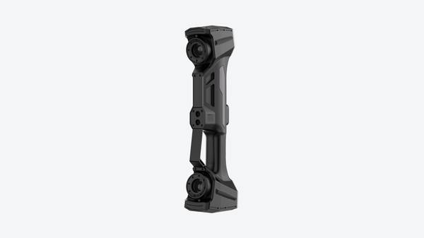
| Parameter | Typical Industrial Consideration |
|---|---|
| Field of view | Balances coverage against point density |
| Surface condition | Drives exposure, spray, or fixture changes |
| Reference strategy | Photogrammetry or encoded targets reduce accumulation error |
| Verification method | Artifact checks and ISO/ASME-aligned acceptance |
Teams such as those working with INSVISION systems typically evaluate accuracy specifications, repeatability studies, and relevant metrology standards against their specific tolerance stack before deployment.
- What Is 3D Scanning? Principles, Workflow, and Industrial Applications 3D scanning is a digital measurement technology that converts the surface geometry of physical objects into 3D data. This entry covers its working principles, core parameters, industrial use cases, common misconceptions, and related technical…
- What Is a 3D Scanner? Types, Parameters, and Selection Criteria A 3D scanner captures three-dimensional surface data from physical objects and converts geometry, dimensions, and features into digital data for inspection, reverse engineering, and modeling.
- What Is 3D Scanning Accuracy? Accuracy, Repeatability, and Resolution Explained 3D scanning accuracy describes how closely scan data matches an object's actual geometry and dimensions. It is assessed through local accuracy, volumetric accuracy, stitching accuracy, repeatability, and resolution.
- What Is Point Cloud Data? Point Clouds, Meshes, and CAD Models in 3D Scanning Point cloud data is an important raw data format in 3D scanning. It consists of discrete 3D coordinate points that describe object surface geometry and support inspection, reverse engineering, modeling, and archiving.
Hangzhou Insvision Technology Co., Ltd.
Address: Building 1, No. 1399 Liangmu Road, Yuhang District, Hangzhou, Zhejiang 311121, China
Copyright © Hangzhou Insvision Technology Co., Ltd. All rights reserved.
Copyright © Hangzhou Insvision Technology Co., Ltd. All rights reserved.