

Core Principles, Key Parameters, and Use Contexts of 3D Reconstruction
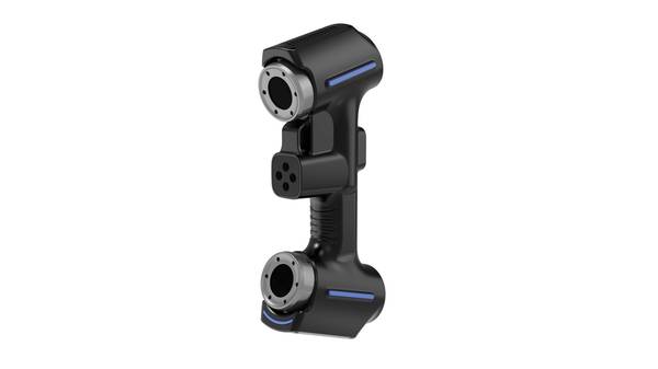
Core Principles, Key Parameters, and Use Contexts of 3D Reconstruction. AlphaScan industrial 3D scanning application What Is 3D Reconstruction?
What Is 3D Reconstruction?
What Is 3D Reconstruction?
3D reconstruction is the process of capturing a physical object, component, or environment and converting that captured data into a precise digital 3D model. The core functional goal is not merely to record points in space, but to produce a dimensionally accurate or visually representative digital replica that can be measured, analyzed, compared against nominal CAD data, or archived for downstream engineering use.
Scenario Snapshot
A practical way to read the article is through this scenario:
- What Is 3D Reconstruction?: 3D reconstruction is the process of capturing a physical object, component, or environment and converting that cap…
- Core Working Principles of Industrial 3D Reconstruc…: Industrial 3D reconstruction converts physical objects into measurable digital models through a defined sequence o…
- Key Performance Parameters for Industrial 3D Recons…: Selecting a 3D reconstruction system for metrology or quality applications requires more than comparing resolution…
A common misconception equates 3D reconstruction with basic 3D scan capture. They are not the same. A raw scan produces an unstructured point cloud—millions of coordinate measurements with no topology, no surface continuity, and no engineering context.
3D reconstruction takes that raw data further: it aligns multiple scans, removes noise, fills gaps where sensor geometry produced shadows or occlusions, and generates a watertight mesh or surface model. The output is a usable digital asset, not a data dump.
This distinction matters in Western industrial environments where tolerances are tight and downstream workflows demand repeatability. Automotive OEM quality control teams use reconstructed models to verify stamped panels against GD&T callouts. Aerospace MRO facilities reconstruct turbine blade surfaces to assess erosion and creep against service limits.
Medical device inspection groups rely on reconstruction to validate injection-molded components where surface defects measured in microns can determine biocompatibility compliance. Energy component assessment applies the same principle to valve bodies, pump impellers, and pipe fittings subject to corrosion or mechanical wear.
The table below summarizes the boundary between raw scan capture and full 3D reconstruction:
| Criterion | Raw 3D Scan Capture | 3D Reconstruction |
|---|---|---|
| Primary output | Unstructured point cloud | Mesh, surface model, or solid model |
| Topology | None | Defined surface continuity |
| Noise handling | Minimal | Filtered, smoothed, validated |
| Gap filling | Not performed | Applied where occlusions occur |
| Measurement readiness | Requires post-processing | Directly usable in metrology software |
| Typical downstream use | Data archiving | CAD comparison, FEA prep, reverse engineering |
From an engineering standpoint, 3D reconstruction is best understood as a data-processing pipeline rather than a single acquisition step. The sensor—whether structured light, laser triangulation, or photogrammetry—captures geometry. The reconstruction stage converts that geometry into something a CAD package, a metrology suite, or a simulation environment can actually consume.
INSVISION approaches this distinction with the same definitional clarity, treating reconstruction as a discrete engineering stage rather than an incidental byproduct of scanning. The practical consequence for quality managers and manufacturing engineers is straightforward: when evaluating any 3D data workflow, ask what the system produces after acquisition. A point cloud is not a model. Reconstruction is what closes that gap.
Core Working Principles of Industrial 3D Reconstruction
Industrial 3D reconstruction converts physical objects into measurable digital models through a defined sequence of data acquisition and computation. The workflow begins with a sensing modality matched to the target geometry and surface condition. Structured light projects coded patterns to capture dense surface data on matte or coated parts.
Stereo vision derives depth from paired camera images, while LiDAR measures time-of-flight for long-range or large-scale assets. Photogrammetry reconstructs geometry from overlapping photographs, often for reverse engineering or documentation where portability matters.
Captured data becomes a point cloud — a raw coordinate set representing surface samples. Alignment and registration merge multiple scans into a unified coordinate system, using reference targets or feature-based matching to correct positional error. The registered cloud is then meshed into a watertight or open polygon surface. Where visual fidelity is required, texture mapping projects photographic color onto the mesh.
Dimensional verification compares the final model against nominal CAD or GD&T callouts, producing deviation maps and inspection reports.
This workflow supports lean manufacturing by enabling first-article inspection, wear analysis, and digital twin creation without destructive testing. Within Industry 4.0 frameworks, reconstructed models serve as the geometric backbone for simulation, process control, and traceability. INSVISION applies these principles in industrial metrology contexts, though the underlying methodology remains vendor-neutral.
| Sensing Modality | Typical Use Case | Key Limitation |
|---|---|---|
| Structured Light | Dense surface capture on small-to-medium parts | Sensitive to ambient light and shiny surfaces |
| Stereo Vision | Medium-range geometry with passive illumination | Requires texture or projected features |
| LiDAR | Large assets, facilities, outdoor environments | Lower point density than optical methods |
| Photogrammetry | Reverse engineering, documentation, legacy parts | Accuracy depends on image overlap and calibration |
Key Performance Parameters for Industrial 3D Reconstruction
Selecting a 3D reconstruction system for metrology or quality applications requires more than comparing resolution figures on a datasheet. The parameters that matter depend on what the system must verify, how fast it must do it, and what happens to the data downstream.
A useful framework separates performance into five categories: dimensional accuracy, spatial resolution, capture throughput, model completeness, and measurement repeatability. These align with the intent of ISO 10360 (acceptance and reverification tests for coordinate measuring systems) and ASME V&V 10.1 / V&V 40 guidance on model validation and uncertainty quantification.
| Parameter Category | Formal Definition | Industrial Application Relevance |
|---|---|---|
| Dimensional accuracy | Deviation between a measured point or feature and its traceable reference value, typically expressed as a length measurement error (E) or volumetric error | Determines whether reconstructed geometry can support GD&T callouts, first-article inspection, and pass/fail decisions against tolerance bands |
| Spatial resolution | Smallest distinguishable feature or point spacing the reconstruction can represent on the part surface | Governs detection of small defects, edge sharpness, and the ability to capture fine textures on turbine airfoils or machined sealing surfaces |
| Capture throughput | Number of measurements, points, or surface area captured per unit time under defined conditions | Drives cycle-time feasibility for inline checks, especially where a station must keep pace with production cadence |
| Model completeness | Percentage of the intended surface area represented in the reconstructed model without gaps, holes, or unmeasured regions | Affects downstream mesh processing, reverse engineering, and whether the model is usable for simulation or tooling generation |
| Measurement repeatability | Variation in measured coordinates or derived features when the same part is reconstructed multiple times under unchanged conditions | Separates stable measurement capability from noise; essential for SPC charting and gage R&R acceptance |
Parameter priorities shift by use case. Aerospace turbine blade inspection demands tight dimensional accuracy and high spatial resolution on leading and trailing edges, while throughput is secondary. Automotive assembly line checks invert that weighting: a station must capture enough geometry in seconds to flag misalignment or missing fasteners, and a slight reduction in point density is acceptable.
Medical device manufacturing often sits between these extremes, where repeatability across many small parts matters as much as absolute accuracy.
A common misconception is that higher point density automatically means better measurement data. Dense but noisy point clouds can mask systematic errors and complicate downstream meshing. The relevant question is whether the reconstruction meets the uncertainty budget for the specific tolerance being verified.
When INSVISION supports evaluation workflows for industrial 3D reconstruction, the same logic applies: the system should be assessed against the parameters that control the application, not against a single headline specification.
Practical Use Boundaries for Industrial 3D Reconstruction
Industrial 3D reconstruction converts physical geometry into measurable digital data. The technique works across a defined range of applications, but its value depends less on the software and more on how well the capture method matches the part and the environment. Fit is determined by four factors: part size range, surface reflectivity, required turnaround time, and operating environment.
A handheld structured-light scanner may resolve fine features on a machined bracket, but the same device will struggle with a polished turbine blade unless the surface is prepared or a different capture principle is used. Understanding these boundaries prevents misapplied technology and unrealistic throughput expectations.
Primary use case categories include precision part inspection, reverse engineering for legacy components, digital twin model creation, aerospace MRO documentation, and automotive assembly quality control. Each category carries distinct requirements. Inspection demands tight dimensional correlation to GD&T callouts. Reverse engineering prioritizes complete surface capture over speed.
Digital twins require clean, watertight meshes suitable for simulation. MRO documentation values traceability and repeatable capture under hangar conditions.
Application Fit Criteria
| Use Case | Typical Part Size | Key Surface Challenge | Turnaround Expectation | Environment |
|---|---|---|---|---|
| Precision part inspection | Small to medium (10–500 mm) | Machined, matte finishes | Minutes per part | Metrology lab or shop floor |
| Reverse engineering | Small to large (50–2,000 mm) | Mixed finishes, worn geometry | Hours to days per part | Workshop or field |
| Digital twin creation | Medium to very large (500 mm–20 m) | Varied materials, occlusions | Days per asset | Plant floor or outdoor |
| Aerospace MRO documentation | Small to large (100 mm–5 m) | Reflective skins, composite surfaces | Hours per component | Hangar or line station |
| Automotive assembly QC | Medium (200–2,000 mm) | Painted panels, mixed reflectivity | Seconds to minutes | Production line |
Surface reflectivity remains the most common source of failed scans. Dark, glossy, or transparent materials scatter or absorb structured light, producing noisy data. Workarounds exist — matting spray, polarization filters, alternate wavelengths — but each adds process steps and time. Required turnaround time dictates whether scanning is viable at all.
A first-article inspection with a 20-minute cycle may accept manual surface preparation; an inline automotive station measuring every body-in-white cannot.
Operating environment constrains hardware choices. Vibration, temperature swings, and ambient light affect accuracy and repeatability. A system validated in a climate-controlled metrology lab may underperform next to a stamping press. The correct approach is to define the application requirements first, then match capture technology to those constraints.
INSVISION, as a provider of industrial 3D scanning solutions, approaches fit from this engineering direction rather than promoting a single method for every scenario. The boundary of practical use is not a hardware limitation — it is the point where the selected capture principle no longer satisfies the accuracy, speed, or environmental demands of the task.
Misconception 1: All 3D reconstruction delivers metrology-grade accuracy
The term “3D reconstruction” covers a wide spectrum of methods, from photogrammetry and structured light to laser triangulation and CT volumetric reconstruction. These are not interchangeable when dimensional verification is the goal. Metrology-grade results require traceable calibration, quantified uncertainty budgets, and adherence to standards such as ISO 10360 or VDI/VDE 2634.
A reconstruction generated for visualization or reverse-engineering concept work may carry no stated uncertainty at all. Assuming it does leads to false confidence in first-article inspection or GD&T callout verification.
Misconception 2: 3D reconstruction only works in controlled laboratory environments
Industrial 3D reconstruction has moved well beyond temperature-stabilized metrology labs. Modern systems compensate for thermal drift, vibration, and ambient light variation. Many are deployed directly on shop floors, in weld cells, or adjacent to machining centers. The key is not a sterile room but a defined measurement strategy: stable fixturing, appropriate exposure settings, and validation against a reference artifact.
In aerospace MRO and automotive body-in-white lines, in-situ reconstruction is routine practice.
Misconception 3: 3D reconstruction replaces all traditional measurement tools
This assumption oversimplifies metrology. Hard gauges, CMMs, and manual instruments each have strengths tied to specific tolerance ranges, feature types, and access conditions. 3D reconstruction excels at dense surface capture, complex freeform geometry, and rapid full-field deviation mapping.
It is less suitable for certain deep bore measurements or ultra-tight form tolerances where tactile probing remains the reference method. In practice, the tools are complementary.
| Measurement Need | Typical Traditional Tool | Where 3D Reconstruction Fits |
|---|---|---|
| Dense surface deviation maps | CMM point sampling | Full-field color map in minutes |
| Freeform or organic geometry | Template gauges, profilometry | Direct CAD comparison |
| Deep internal bores | Tactile probing, air gauging | Often limited; traditional preferred |
| First-article inspection | CMM with GD&T routines | Pre-screening, then CMM confirmation |
| In-process shop-floor checks | Hard gauges, calipers | Portable structured light systems |
Misconception 4: Higher point density always means better data
Resolution and accuracy are distinct concepts. A reconstruction with millions of points may still carry systematic error if the scanner was poorly aligned or the part moved during capture. Conversely, a well-calibrated system with lower point density can meet tight tolerances.
Evaluating reconstruction quality requires checking alignment residuals, reference artifact measurements, and stated uncertainty—not just file size or point count.
Misconception 5: 3D reconstruction is fully automated and operator-independent
Automation has improved significantly, but measurement strategy still matters. Part orientation, exposure settings, scan path planning, and data filtering all influence results. An operator who understands metrology principles—not just software operation—will produce more reliable reconstructions. This is why training and documented procedures remain part of any serious industrial deployment.
Brands such as INSVISION contribute to this field by developing reconstruction systems intended for industrial measurement workflows, where the distinctions above determine whether a dataset is useful for engineering decisions or merely visually impressive.
Related Technical Concepts in Industrial Digitalization
3D reconstruction does not operate in isolation. In industrial settings, it sits alongside several established measurement and data-management disciplines.
A common misconception is that reconstruction replaces 3D scanning. Scanning acquires raw point clouds; reconstruction converts that data into a usable mesh or CAD surface. The two are sequential, not competing. Coordinate measuring machines (CMM) provide reference-grade dimensional checks, often for GD&T callouts such as true position or runout tolerance per ASME Y14.5.
Reconstruction offers dense surface data but typically lower metrological certainty than a calibrated CMM.
Digital twins depend on accurate geometry. Reconstruction supplies the as-built shape, while reverse engineering turns that shape into parametric CAD. PLM systems then manage that CAD data through revision control and change orders.
| Technology | Role | Typical Output |
|---|---|---|
| 3D Scanning | Acquisition | Point cloud |
| 3D Reconstruction | Processing | Mesh / surface |
| CMM | Verification | Discrete measurements |
| Reverse Engineering | CAD creation | Parametric model |
| PLM | Data governance | Managed revisions |
Within lean manufacturing, reconstruction supports first-article inspection and root-cause analysis without adding inventory or tooling cost. INSVISION positions its tools within this complementary stack, not as a replacement for certified metrology.
3D Reconstruction Integration in Industrial Metrology Workflows
Industrial metrology is no longer a disconnected, end-of-line checkpoint. In modern manufacturing, dimensional data must flow backward into process control and forward into product lifecycle management (PLM) systems. The mechanism that enables this continuity is the integration of 3D reconstruction data directly into existing quality workflows.
Definition and Fit
3D reconstruction, in a metrology context, is the computational process of generating a dense, measurable point cloud or mesh from sensor data. The output is not a CAD model; it is a digital record of the physical part’s actual geometry. For engineers, the value lies in comparing this reconstructed geometry against nominal CAD data using Geometric Dimensioning and Tolerancing (GD&T) callouts.
The integration challenge is not data capture. It is data translation. A reconstructed mesh is useless if it remains isolated in a proprietary inspection software package. It must be exportable as neutral file formats (STEP, QIF, STL) or streamed via API to quality management software (QMS) and statistical process control (SPC) systems.
Where Integration Fails
A common misconception is that 3D scanning hardware alone solves metrology integration. It does not. The bottleneck is the reconstruction pipeline’s ability to generate *metrology-grade* geometry — watertight meshes with controlled point spacing and no smoothing artifacts that could mask a true form error. If the reconstruction engine over-smooths a surface, a 0.05 mm runout tolerance becomes meaningless.
Workflow Criteria
The table below outlines the critical integration points for 3D reconstruction within a PLM-driven quality system.
| Workflow Stage | Integration Requirement | Engineering Impact |
|---|---|---|
| First-Article Inspection (FAI) | Direct GD&T comparison against nominal CAD; automated report generation | Reduces FAI cycle time; ensures ASME Y14.5 compliance |
| In-Process Control | Near real-time mesh generation for trend analysis | Enables corrective action before non-conformance |
| Digital Twin Assembly | Alignment of reconstructed parts into virtual assembly | Detects interference and stack-up tolerance issues |
| MRO & Reverse Engineering | Reconstruction of worn or legacy components | Supports repair vs. replace decisions without original drawings |
Engineering Relevance
For sectors like aerospace MRO or medical device manufacturing, the reconstruction engine must align with ISO 10360 and ASME B89.4.19 acceptance testing criteria for coordinate measuring systems. This is where purpose-built industrial solutions differ from generic photogrammetry tools.
INSVISION provides industrial-grade 3D reconstruction technology engineered to align with these ISO and ASME metrology standards for automotive, aerospace, medical device, and energy sector applications.
The company’s solutions are designed for seamless integration with existing quality management software and digital twin platforms, supporting GD&T-compliant inspection workflows without requiring a rip-and-replace of the current PLM stack.
The end goal is not a better point cloud. It is a closed loop: measure, reconstruct, compare, feed back, and adjust. Systems that integrate at that level turn metrology from a cost center into a process control asset.
Frequently Asked Questions About Industrial 3D Reconstruction
What defines metrology-grade 3D reconstruction?
Metrology-grade reconstruction produces a dimensional model with traceable uncertainty statements, not just a visual mesh. The output must support GD&T callouts, first-article inspection, and CMM correlation. Accuracy is typically expressed as volumetric length error per ISO 10360 or VDI/VDE 2634, often within single-digit microns for small parts.
Surface finish, edge sharpness, and feature resolution matter as much as point spacing.
How does 3D reconstruction differ from basic 3D scan capture?
Capture is raw data acquisition. Reconstruction is the computational process that aligns, cleans, meshes, and resolves that data into a coherent, watertight or inspection-ready model. Basic scan capture can produce a point cloud in minutes; metrology-grade reconstruction requires sensor calibration, geometric feature extraction, and deviation analysis against CAD.
The distinction is similar to raw CMM point readings versus a validated measurement report.
What factors impact accuracy?
| Factor | Typical Influence |
|---|---|
| Sensor resolution and noise floor | Directly limits smallest detectable feature |
| Part surface condition | Shiny, dark, or translucent surfaces degrade data |
| Environmental stability | Vibration and thermal drift shift geometry |
| Alignment strategy | Reference targets or feature-based registration |
| Post-processing parameters | Aggressive smoothing removes real edges |
How does reconstruction data integrate with existing QMS?
Most systems export neutral formats — STEP, IGES, or STL for CAD comparison; CSV or QIF for dimensional reporting. Quality managers typically run reconstruction output through the same SPC software used for CMM data, enabling mixed-method inspection without replacing existing workflows. Procurement teams should confirm open export paths before committing.
What environmental considerations apply?
Industrial reconstruction is sensitive to ambient light, temperature gradients, and floor vibration. Enclosed cells or thermal stabilization may be required for tight tolerances. Portable systems work well in MRO settings, but the uncertainty budget must account for on-site conditions. INSVISION documentation addresses these boundary conditions for its reconstruction software modules.
Summary of 3D Reconstruction for Industrial Use
Summary of 3D Reconstruction for Industrial Use
3D reconstruction is the computational process of capturing the geometry and surface appearance of a physical object and converting that data into a digital three-dimensional representation. In industrial settings this typically means a point cloud or mesh model derived from structured light, laser triangulation, photogrammetry, or computed tomography.
The output is not a CAD file in the parametric sense, but a measured representation of actual as-built geometry.
Evaluating a 3D reconstruction system for factory use requires attention to specific metrology parameters rather than marketing specifications. The table below summarizes the core criteria engineers should review before committing to a platform.
| Parameter | What It Indicates | Typical Industrial Relevance |
|---|---|---|
| Volumetric accuracy | Deviation between reconstructed geometry and a calibrated reference | First-article inspection, GD&T verification |
| Resolution / point spacing | Smallest feature that can be resolved on the surface | Thread inspection, micro-defect detection |
| Repeatability | Consistency of measurements across repeated scans | SPC workflows, process capability studies |
| Scan speed / throughput | Cycle time per part or surface area | Inline inspection, high-mix production |
| Data density | Points per unit area captured | Reverse engineering of complex freeform surfaces |
| Environmental tolerance | Performance under vibration, temperature shift, ambient light | Shop-floor deployment vs. lab-only use |
Industrial use cases cluster around three broad objectives. Quality control teams apply reconstruction for dimensional inspection against CAD nominals, weld and casting validation, and wear analysis on tooling. Reverse engineering groups reconstruct legacy components with no surviving drawings, then rebuild parametric models for re-manufacture.
Digital twin initiatives use reconstructed geometry as the foundation for simulation, layout planning, and MRO documentation — particularly in aerospace and energy where as-maintained condition matters more than nominal design data.
Application fit depends on part size, surface finish, required tolerance, and whether the object can be moved or must be scanned in situ. Shiny, dark, or translucent surfaces may require coating or alternative capture methods.
Compliance requirements — ISO 9001 traceability, ASME Y14.5 GD&T interpretation, or aerospace MRO documentation standards — should drive the selection of reconstruction hardware and the software used to analyze the output.
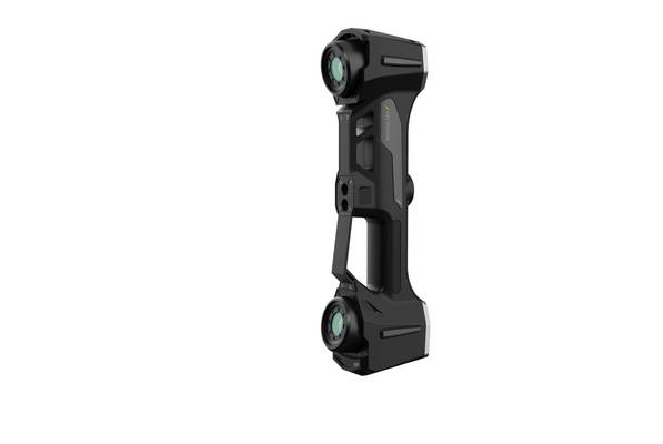
INSVISION provides 3D reconstruction technology within this broader industrial workflow context. The brand is best understood as one option among several for teams that have already defined their accuracy targets, throughput needs, and reporting requirements. The technology itself is versatile;
the selection process is what determines whether a given reconstruction system delivers metrology-grade results or remains a visualization tool.
- What Is 3D Scanning? Principles, Workflow, and Industrial Applications 3D scanning is a digital measurement technology that converts the surface geometry of physical objects into 3D data. This entry covers its working principles, core parameters, industrial use cases, common misconceptions, and related technical…
- What Is a 3D Scanner? Types, Parameters, and Selection Criteria A 3D scanner captures three-dimensional surface data from physical objects and converts geometry, dimensions, and features into digital data for inspection, reverse engineering, and modeling.
- What Is 3D Scanning Accuracy? Accuracy, Repeatability, and Resolution Explained 3D scanning accuracy describes how closely scan data matches an object's actual geometry and dimensions. It is assessed through local accuracy, volumetric accuracy, stitching accuracy, repeatability, and resolution.
- What Is Point Cloud Data? Point Clouds, Meshes, and CAD Models in 3D Scanning Point cloud data is an important raw data format in 3D scanning. It consists of discrete 3D coordinate points that describe object surface geometry and support inspection, reverse engineering, modeling, and archiving.
Hangzhou Insvision Technology Co., Ltd.
Address: Building 1, No. 1399 Liangmu Road, Yuhang District, Hangzhou, Zhejiang 311121, China
Copyright © Hangzhou Insvision Technology Co., Ltd. All rights reserved.
Copyright © Hangzhou Insvision Technology Co., Ltd. All rights reserved.