

Metrology 3D Scanning Implementation Checks to Avoid Workflow Gaps
metrology 3d scanning: Hidden Delivery Risks in Metrology 3D Scanning Rollouts Hidden Delivery Risks in Metrology 3D Scanning Rollouts A quality manager.
Hidden Delivery Risks in Metrology 3D Scanning Rollouts
A quality manager signs off on a new structured light scanner after the demo looks flawless. Six months later, the system sits idle more than it runs. The parts are there. The CAD models are there. The scanner still meets its published accuracy specs on the calibration plate.
But the data coming off the shop floor doesn’t match what the CMM reports, and the inspection reports don’t drop into the existing quality system without manual rework.
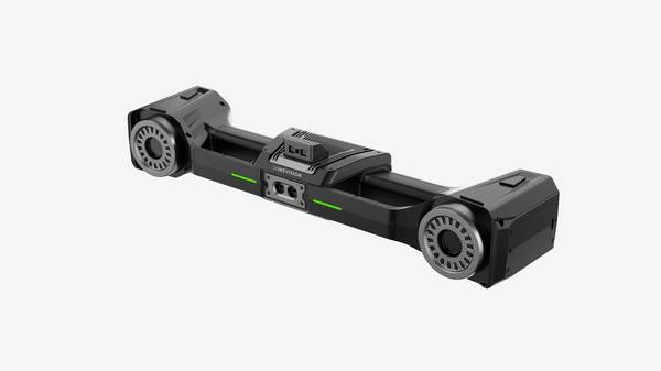
Selection Dimensions and Field Checks
| Focus Area | Decision Point | Deployment Note |
|---|---|---|
| Hidden Delivery Risks in Metrology 3D Scanning Rollouts | A quality manager signs off on a new structured light scanner after the demo looks flawless. | Six months later, the system sits idle more than it runs. |
| Sample Validation: Aligning Scanning Performance with R… | The decision to deploy metrology 3D scanning on a production line should never rest on a datasheet alone. | The scanner that performs well on a clean calibration artifact in a lab may struggle with the same part family once it has coolant residue, rele… |
| Integrating Metrology 3D Scanning into Established Qual… | The key takeaway is straightforward: metrology 3D scanning earns its place in a quality workflow only when it reduces decision latency without adding… | Most mature plants already have functional quality gates. |
| Training and Post-Deployment Review for Consistent Metr… | A scanner is only as consistent as the people running it. | That sounds obvious, but plenty of plants treat metrology 3D scanning as a plug-and-play purchase. |
This is the gap between buying metrology 3D scanning hardware and actually deploying it as a measurement process.
Western manufacturing teams often assume that if the hardware meets the spec sheet, the rollout will take care of itself. In practice, most underperforming deployments trace back to three risks that have little to do with the scanner’s nominal accuracy and everything to do with how the equipment fits into an existing quality workflow.
The first risk is accuracy misalignment. A scanner can deliver volumetric accuracy figures that look strong in a controlled lab, yet still fail to hold the tolerances a drawing actually requires once you account for datum alignment, feature size, surface finish, and the measurement strategy used to extract GD&T callouts.
ISO 17025 calibration certificates and ASME Y14.5-based inspection requirements don’t automatically translate to scanner performance on a specific part geometry. The question isn’t whether the scanner meets its published spec. It’s whether the scanner’s measurement uncertainty budget fits the tolerance band on the features you actually inspect.
The second risk is data pipeline incompatibility. Metrology 3D scanning generates point clouds and meshes, not the discrete feature measurements that many quality systems expect. If the scan-to-report workflow requires exporting raw data, cleaning it in separate software, manually extracting features, and then re-entering results into an SPC or MES platform, the process breaks down quickly.
Engineers tolerate this for a few weeks. They won’t tolerate it as a permanent inspection method.
The third risk is environmental. Automotive OEM plants, aerospace MRO hangars, and medical device production areas all introduce vibration, temperature swings, and ambient light conditions that lab demos don’t replicate.
A scanner that performs well in a metrology lab may drift or lose data quality when a forklift rumbles past, when a bay door opens and changes the thermal gradient, or when overhead lighting interferes with structured light projection. None of these issues appear on a hardware spec sheet.
Procurement teams that focus solely on resolution, accuracy, and scan speed during vendor selection inherit these problems after purchase. Integration stalls. Rework climbs. The scanner becomes a niche tool for occasional reverse engineering instead of a production measurement asset.
The fix isn’t more hardware. It’s a delivery process that treats metrology 3D scanning as a quality workflow integration project, not a box drop. That means validating accuracy against the actual part tolerances, mapping the scan-to-report data flow before rollout, and testing on the real shop floor under real conditions.
INSVISION approaches scanner delivery with this workflow-first lens, because a scanner that doesn’t fit the quality system is just expensive shelfware.
Sample Validation: Aligning Scanning Performance with Real-World Part Requirements
The decision to deploy metrology 3D scanning on a production line should never rest on a datasheet alone. The scanner that performs well on a clean calibration artifact in a lab may struggle with the same part family once it has coolant residue, release agent, or shop-floor vibration in play. Sample validation closes that gap.
It is the structured process of proving, before full deployment, that a given scanner can hit the dimensional accuracy, scan completeness, and throughput targets your actual parts demand under your actual production conditions. Skipping this step is how factories end up with inspection bottlenecks, rejected data sets, and quality engineers who quietly revert to manual gauging.
Done properly, sample validation turns a technology evaluation into an engineering decision.
Cross-functional teams should approach validation from three angles simultaneously. Quality engineering owns the accuracy question: does the scan data agree with calibrated reference measurements? For aerospace turbine blades, that means comparing scanned airfoil profiles against CMM data on the same features, with attention to form deviation and leading-edge definition.
For medical implants, it means verifying that tolerance verification on complex freeform surfaces falls within the uncertainty budget the part drawing allows. Procurement needs to confirm the scanner can handle the material mix in the factory, not just the easiest sample. Reflective aerospace alloys, medical-grade polymers, and painted automotive body panels each present different optical challenges.
A scanner that captures a matte aluminum bracket cleanly may produce noisy data on a polished titanium surface without the right exposure strategy or surface preparation protocol.
Scan completeness matters as much as accuracy. Undercuts, deep cavities, and fine surface features are where many scanners fall short, and the only way to know is to run the geometry. A validation workflow should include a completeness check: scan the part, mesh the data, and overlay the result against the CAD model to identify missing regions.
If a turbine blade cooling channel or an implant bone-ingrowth lattice fails to reconstruct, the scanner is not ready for that application regardless of its nominal accuracy specification.
The validation must replicate production reality. Fixturing setups should match how parts will actually be held on the line. Environmental variables, including ambient light, temperature drift, and floor vibration, should be present during testing, not eliminated for convenience. Throughput targets need to be measured against the full workflow: part loading, scan, alignment, mesh generation, and report output.
A scanner that takes ninety seconds to capture a part but requires ten minutes of manual post-processing may fail the cycle time requirement even if the raw scan speed looks impressive.
INSVISION guides customers through structured sample validation workflows designed to confirm that scanning performance matches specific part and quality requirements before full deployment. The goal is not to demonstrate the scanner in ideal conditions but to de-risk the implementation by finding the failure modes early.
That is the difference between a successful metrology 3D scanning rollout and an expensive piece of equipment sitting idle on a cart.
Integrating Metrology 3D Scanning into Established Quality Workflows
The key takeaway is straightforward: metrology 3D scanning earns its place in a quality workflow only when it reduces decision latency without adding inspection overhead. Most mature plants already have functional quality gates. The implementation challenge is not proving that a scanner can capture data.
It is proving that the data flows into existing QMS structures, GD&T reporting formats, and lean operating rhythms without forcing engineers to rework their documentation logic.
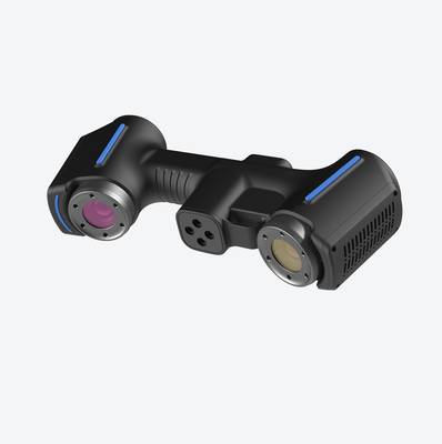
Start with touchpoint mapping. Incoming material inspection typically needs fast dimensional verification against supplier prints. In-process checks require localized feature evaluation near the machine or cell. Final product audits demand full-surface data tied to ballooned drawings or CMM-style reports.
Aerospace MRO damage assessment introduces a different constraint: scanning irregular, worn, or deformed surfaces where nominal CAD is often incomplete. Each touchpoint has a different tolerance expectation, data density requirement, and report consumer.
Before positioning any scanning station, the quality team should define what each gate must output. That output drives scanner selection, fixture strategy, and software configuration. A scanner that produces dense point clouds but cannot export an ISO/ASME-compliant GD&T report will stall at the QMS boundary.
Conversely, a scanner configured only for color maps may fail when the customer requires numeric pass/fail values tied to specific datum references.
The practical integration sequence usually follows three phases. First, run parallel trials against the existing method—CMM, gauge, or manual layout—without changing release authority. Collect data on correlation, repeatability, and operator time. Second, align the scan software’s report templates with internal and customer-mandated formats. This means matching feature labels, datum callouts, tolerance bands, and export paths.
Third, move the scanner into the release loop for defined part families or defect categories, not for every dimension at once.
Data interface alignment is where many implementations slow down. QMS platforms differ in how they consume inspection records. Some accept PDF reports only; others require structured CSV or database fields. The scanning system should be evaluated on whether it can output stable, traceable records that match the plant’s existing nonconformance and traceability logic.
If the scanner forces a parallel spreadsheet or a separate viewer, the lean benefit erodes quickly.
Site adaptation matters more than scanner specifications in many cases. A scanning station placed at the end of a line creates a bottleneck if operators must walk parts to it. A station positioned next to a machining cell can catch drift before a batch runs out of tolerance. Vibration, ambient light, temperature swings, and part handling access all affect practical repeatability.
These factors should be assessed during a pre-installation walkthrough, not after the equipment arrives.
INSVISION industrial 3D scanners fit into this model when the inspection task requires dense surface data from complex geometries that would be slow or impractical to probe point-by-point. The value lies in capturing enough measured points to characterize form, profile, and local deviation across freeform surfaces, then converting that data into reports that quality engineers can release without translation work.
The scanner should be treated as a data source feeding the existing quality system, not as a replacement for the QMS itself.
Lean continuous improvement principles apply directly here. A scanning workflow that reduces setup time versus hard gauging can shorten inspection cycles. A scanner that detects a forming trend early can prevent downstream rework. But those gains only materialize when the station is positioned where the information changes a decision.
Installing a scanner without defining what action its output triggers tends to add cost without reducing risk. The implementation should be judged by whether it closes the loop between measurement and correction faster than the previous method.
Common integration pitfalls include over-scanning parts where a few critical features matter, under-defining report templates before rollout, and neglecting operator training on part alignment and fixture repeatability. These are workflow issues, not scanner issues. The equipment can be capable and still fail to deliver value if the surrounding process is not adapted.
In practice, the most successful integrations start small. One part family, one quality gate, one report format. Prove correlation against the existing method, document the time savings or coverage improvement, then expand to adjacent applications. That approach respects an established quality system while allowing metrology 3D scanning to demonstrate where it genuinely reduces inspection uncertainty.
Training and Post-Deployment Review for Consistent Metrology Performance
A scanner is only as consistent as the people running it. That sounds obvious, but plenty of plants treat metrology 3D scanning as a plug-and-play purchase. A new system arrives, gets handed to the quality lab, and within a few months the results drift. Not because the hardware failed, but because no one defined who needs to know what.
The truth is that scan data quality depends on three very different user groups, and each one needs a different kind of training to keep the system trustworthy.
Metrology technicians carry the deepest technical load. They plan scan paths, set resolution and exposure for different surface finishes, manage alignment strategies, and process point clouds into usable inspection data. Their training should cover advanced scan planning, data cleanup without over-filtering real geometry, and routine calibration checks tied to a documented schedule.
If technicians do not understand how ambient temperature, part fixturing, or shiny versus matte surfaces affect scan noise, the downstream data becomes unreliable even when the scanner itself is fine.
Quality engineers need a different focus. They rarely run the scanner, but they interpret the output against GD&T callouts and customer or regulatory requirements. Training for this group centers on report interpretation, datum alignment verification, and knowing when a deviation is real versus a scanning artifact.
A quality engineer who understands the boundary conditions of metrology 3D scanning can push back on bad data before it reaches a PPAP submission or first-article report.
Production staff need the lightest but most repeatable training. Their job is part loading, scan initiation, and keeping throughput moving for in-process checks. They do not need deep point-cloud theory. They need a simple, repeatable routine: load the part in the fixture, start the program, confirm the scan completed, flag anything unusual.
When production operators understand the basics of what a good scan looks like, they catch fixture shifts or dirty optics early instead of passing bad data down the line.
Post-deployment review keeps all of this from decaying. The best teams schedule regular performance audits against the same sample parts used during initial validation. If a calibrated artifact measured within tolerance at installation, it should measure within tolerance six months later.
When it does not, the audit points to the cause: a bumped scanner, a worn fixture, a software update that changed filtering defaults, or an operator shortcut that crept into the workflow.
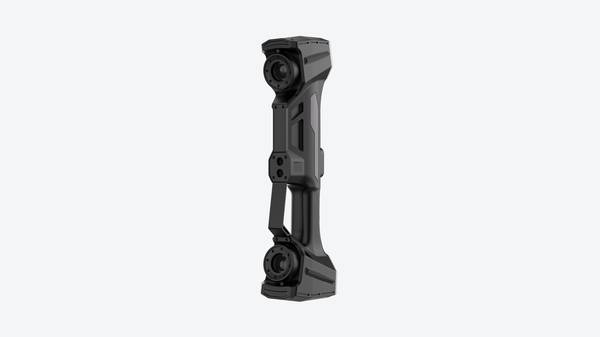
Troubleshooting common on-site issues is part of that review. Most problems are not dramatic. A scan that suddenly shows excessive noise on one side of a part usually means a dirty lens or a changed lighting condition. A recurring alignment failure often traces back to a fixture that shifted or a part not seated fully.
Review sessions should walk through these failure modes with the people who actually run the equipment, not just the engineering team.
Workflows also need adjustment as production requirements change. A line that adds a new material, a new part family, or a faster takt time may need revised scan parameters, different fixturing, or a simplified inspection routine. The original validation is not a one-time event. It is a baseline that should be revisited whenever the process around the scanner changes.
INSVISION provides structured, role-aligned training and post-implementation review support specifically for industrial 3D scanning deployments. The goal is not to turn every operator into a metrology expert. It is to give each role the right level of knowledge so the system produces consistent, compliant data over time. That is the difference between owning a scanner and running a reliable measurement process.
Sustaining Long-Term Value in Metrology 3D Scanning Workflows
The long-term value of metrology 3D scanning does not come from the scanner alone. It comes from the workflow built around it. A scanner can deliver excellent point clouds on day one and still produce unreliable inspection data six months later if the supporting processes are not controlled.
Sustaining performance across multiple production lines requires attention to three operational conditions: calibration discipline, environmental stability, and scan planning reuse.
Calibration schedules should follow metrology best practices rather than arbitrary calendar dates. The appropriate interval depends on scanner usage intensity, thermal cycling in the facility, and whether the unit moves between stations or stays fixed. A scanner used daily in an automotive body shop will need verification more often than one used weekly in a lab.
Many quality teams align verification intervals with existing CMM calibration cycles so that all measurement equipment in the plant follows one controlled schedule. This simplifies audit preparation and ensures that any drift in the scanning system is caught before it affects inspection decisions.
Environmental control is equally important, particularly for shop floor deployments. Metrology 3D scanning is sensitive to temperature swings, vibration, and ambient light conditions. A scanning station placed near a bay door or a machining center will see more variability than one in a controlled inspection room. The practical solution is not to demand laboratory conditions everywhere.
It is to define acceptable operating envelopes for each station, monitor those conditions, and document when scans occur outside the envelope. Simple measures such as thermal stabilization time for parts, shielding from direct sunlight, and vibration isolation pads can extend reliable operation significantly.
The third condition is standardized scan planning. Most factories inspect repeat part families: door panels, cylinder heads, turbine blades, brackets, housings. Without a stored scan plan, each new job starts from scratch. An operator repositions the part, adjusts exposure settings, and selects scan regions manually. This adds setup time and introduces variation between operators.
A standardized scan planning library removes that variation. For each part family, the plan defines scanner positioning, resolution settings, datum alignment strategy, and the specific GD&T callouts to be evaluated. When a new lot arrives, the operator loads the plan, confirms the part is staged correctly, and scans. The result is repeatable data, faster throughput, and less dependence on individual operator skill.
Scaling metrology 3D scanning across production lines follows the same logic. A system that starts in one work cell for automotive body panel inspection can extend to powertrain component checks once the scan plans, environmental controls, and calibration routines are established. The technology does not change; the workflow template does.
Similarly, an aerospace MRO operation that begins with single-part damage assessment can scale to fleet-wide inspection programs by building a scan plan library for each component type and defining acceptance criteria in advance. The key is to treat scanning as a managed measurement process, not a standalone tool.
Compliance with industry standards such as ISO 9001, AS9100, or IATF 16949 requires documented evidence of measurement process control. Calibration records, environmental monitoring logs, and controlled scan plans all contribute to that evidence.
When a quality manager can show that scanning workflows follow the same discipline as CMM inspection, the data gains acceptance in first-article inspection, production part approval, and supplier quality audits.
INSVISION supports this structured delivery approach by providing industrial 3D scanning systems that integrate into existing quality workflows rather than requiring a parallel inspection process. The value is not in isolated scanning capability but in consistent, documented, repeatable measurement output.
Structured workflow-focused delivery reduces total cost of ownership because setup time drops, rework from inconsistent scans decreases, and the system scales from one use case to many without reengineering the entire quality process. In lean manufacturing terms, this is waste reduction applied to measurement.
In Industry 4.0 terms, it is the foundation for trusted digital inspection data that can feed statistical process control and continuous improvement initiatives. The scanner is the starting point. The workflow is what sustains the value.
Common Metrology 3D Scanning Delivery Questions
The metrology 3D scanning questions that surface during delivery are almost never about the scanner itself. They are about how the data behaves inside an existing quality system. Procurement teams want to know whether scan results will align with CMM records, and quality engineers need to know what training is actually required before scan data can appear in a customer PPAP or first-article report.
The practical answer is that alignment depends less on the scanner and more on the inspection plan. If GD&T callouts, datum structures, and alignment routines are defined consistently with existing CMM programs, scan data can be compared against the same tolerance framework. The scanner becomes a faster data acquisition front end, not a separate measurement philosophy.
Teams should validate a few known artifacts or production parts against CMM results before switching any workflow.
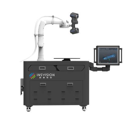
Training for quality teams usually falls into three areas: scanner operation, inspection software, and reporting. Most Western quality groups already understand GD&T and customer reporting formats. What they need is enough software familiarity to extract the right features and export data into existing QMS or SPC platforms.
A practical rollout often starts with one pilot part family, then expands once repeatability and reporting are proven. INSVISION supports this transition by keeping scan data in standard formats that can move into existing quality workflows without forcing a separate reporting ecosystem.
Hangzhou Insvision Technology Co., Ltd.
Address: Building 1, No. 1399 Liangmu Road, Yuhang District, Hangzhou, Zhejiang 311121, China
Copyright © Hangzhou Insvision Technology Co., Ltd. All rights reserved.
Copyright © Hangzhou Insvision Technology Co., Ltd. All rights reserved.