

reverse engineer 3D scan: Practical Criteria for Manufacturing Teams
reverse engineer 3d scan: Common Reverse Engineer 3D Scan Task Classes in Discrete Manufacturing Common Reverse Engineer 3D Scan Task Classes in Discrete.
Common Reverse Engineer 3D Scan Task Classes in Discrete Manufacturing
Western engineering and procurement teams rarely start a reverse engineering project with a blank sheet. More often, they start with a broken casting, a discontinued actuator housing, or a prototype that has drifted from its nominal CAD model. The task is not simply to measure a part.
The task is to recover enough dimensional and geometric information to make a sound engineering decision: can this part be remanufactured, modified, validated, or brought into a digital twin environment without introducing downstream risk?
Common Questions
What should teams check when evaluating Common Reverse Engineer 3D Scan Task Classes in Discrete Manufacturing?
Western engineering and procurement teams rarely start a reverse engineering project with a blank sheet.
What should teams check when evaluating Core Constraints That Define Reverse Engineer 3D Scan Solution Requirem…?
Before a team commits to a handheld scanner, a structured self-assessment saves more time than any demo.
What should teams check when evaluating INSVISION Reverse Engineer 3D Scan Solution Routing by Use Case?
Reverse engineering workflows rarely fail because the scanner cannot capture points.
Across automotive OEM, aerospace MRO, and medical device manufacturing, four reverse engineering task classes consistently justify investment in 3D scan data. The first is legacy part replication for discontinued components. A Tier 1 supplier may need to reproduce a bracket or manifold that was last produced fifteen years ago. The original tooling is gone.
The 2D drawing set is incomplete or dimensioned from an obsolete datum scheme. A handheld 3D scanner captures the full surface envelope in hours, giving the engineering team a mesh that can be compared against whatever scant CAD or drawing data still exists.
The second task class is aftermarket performance part development. In motorsport and specialty automotive work, engineers frequently scan an existing intake, suspension knuckle, or body panel to design a mating component or an improved replacement. The scan does not replace design intent. It provides the as-built geometry that becomes the reference for new CAD work.
Without that reference, even a skilled designer wastes days guessing at fillet radii, draft angles, and mounting hole positions.
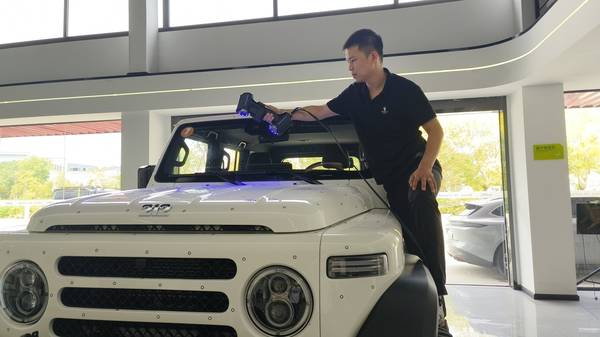
The third class is prototype design validation. During development, 3D-printed or machined prototypes often deviate from nominal in ways that matter for fit and function. A 3D scan of the prototype, overlaid on the CAD model with GD&T callouts, shows exactly where warpage or machining error occurred. This is not the same as a CMM report. A CMM checks discrete points.
A scan shows the full surface, which is what actually mates with adjacent components.
The fourth class is digital twin seed model creation. Plants that want to build simulation-ready models of existing equipment often lack CAD for older machines. Scanning those machines creates the seed geometry for finite element analysis, clearance studies, or retrofit design. In aerospace MRO, this same workflow supports damage mapping and repair scoping on airframe structures.
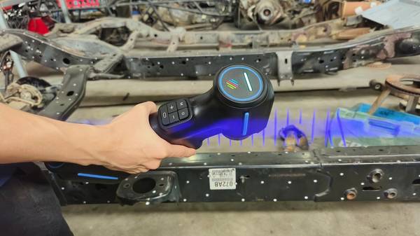
Traditional reverse engineering methods struggle with these tasks. Manual caliper measurement is slow and misses freeform surfaces entirely. Fixed CMM access is limited for large parts or field work. Incomplete 2D drawing sets leave gaps that force assumptions. For teams working to ISO and ASME GD&T standards, those assumptions carry real compliance risk.
A 3D scan reduces that risk by capturing the actual part geometry before any modeling decision is made.
INSVISION AlphaScan fits these task classes because it is built for part-level reverse engineering where surface detail, scan density, and portability matter. The scanner handles the range of part sizes common in discrete manufacturing, from small medical device housings to larger automotive castings.
Its data output moves directly into standard reverse engineering software for mesh cleanup, NURBS surfacing, or solid model creation. For teams evaluating a reverse engineer 3D scan workflow, the practical question is whether the scanner can capture enough detail in the available time. AlphaScan is designed to do exactly that across mixed material surfaces and moderate shop-floor lighting conditions.
The operational value shows up in cycle time and rework avoidance. A legacy part that once required days of manual layout and iterative CAD guessing can often be scanned and modeled in a single shift. A prototype validation scan can be completed before the next design review. A digital twin seed model can be created without taking the machine out of service for extended measurement sessions. These are not theoretical gains.
They are the direct result of replacing sparse point measurement with dense surface capture.
For Western engineering teams, the deciding factor is not scanner speed alone. It is whether the scan data holds up under GD&T evaluation and downstream CAD workflows. That is why the selection criteria should focus on scan resolution, mesh quality, and software compatibility. INSVISION AlphaScan addresses these criteria without forcing a specialized metrology lab setup.
The result is a reverse engineering workflow that fits the way discrete manufacturers actually work: on the shop floor, under time pressure, and with parts that do not match their drawings.
Core Constraints That Define Reverse Engineer 3D Scan Solution Requirements
Before a team commits to a handheld scanner, a structured self-assessment saves more time than any demo. In pre-sales conversations, the useful questions are rarely about raw accuracy claims. They are about how the tool behaves in a specific bay, at a specific cadence, on a specific part family.
Five dimensions consistently separate a reverse engineer 3D scan workflow that holds up on the shop floor from one that only works in a lab.
Part size range dictates coverage strategy and data density. Reverse engineering a large vehicle assembly demands wide field-of-view capture and stable registration across long surfaces. A small precision transmission component needs dense point spacing to resolve fine feature transitions, fillets, and bore geometry.
Teams should define the largest and smallest parts they expect to scan in the same shift, then evaluate whether one scanner can handle both without swapping lenses or changing workflows.
On-site mobility and shop floor access change everything. A repair bay, an aerospace MRO cell, or a stamping line rarely offers a clean metrology room. The scanner has to move to the asset, not the other way around. That means a portable 3D scanner for reverse engineering must tolerate vibration, variable lighting, dust, and tight clearances.
If the system requires a tripod, external tracker, or controlled temperature band, the evaluation should account for setup time at each location.
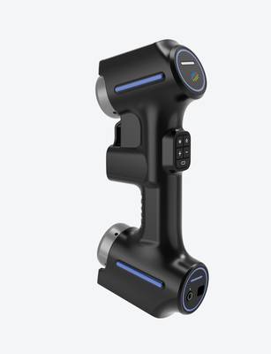
Marker placement feasibility is often ignored until the first failed scan. Some parts arrive coated, oily, reflective, or with no stable reference geometry. If the surface cannot be marked, the scanner must rely on geometry-based tracking. If markers are allowed, the team needs to know how many are required and how placement affects downstream mesh quality.
For high-gloss machined surfaces, markerless tracking may drift unless the software has strong feature recognition.
Per-part takt time targets determine whether scanning fits into production or stays in a lab. A quality engineer checking one casting per hour has different needs than a team scanning 40 brackets per shift. Scan speed matters, but so does the transition between parts: data export, alignment, and mesh cleanup. If the deliverable is a CAD-ready surface, processing time often exceeds scan time.
Batch repeatability needs separate one-off reverse engineering from recurring inspection. A single legacy part can tolerate manual alignment and slower processing. A 3D scan for high-batch reverse engineering requires consistent setup, repeatable coordinate systems, and minimal operator judgment. Teams should test the same part three times and compare deviation maps before accepting a system for repeat use.
INSVISION positions the AlphaScan handheld 3D scanner for teams working across these constraints. It supports large-area capture without losing detail on smaller features, and its portability suits on-site repair and MRO work where parts cannot be moved.
For buyers evaluating reverse engineer 3D scan options, the practical path is to run a small pilot across the five dimensions above, using real parts from the line rather than demo blocks. That pilot tells more about fit than any specification sheet.
INSVISION Reverse Engineer 3D Scan Solution Routing by Use Case
Reverse engineering workflows rarely fail because the scanner cannot capture points. They fail when the tool does not match the part. A handheld scanner that works beautifully on a cast bracket becomes the wrong choice when you are standing next to a six-meter weldment, and a high-precision tracked system is overkill when you only need an STL for a plastic cover.
INSVISION routes reverse engineering projects by four practical constraints: part size, site freedom, tolerance band, and batch repeatability. The table below maps each promoted INSVISION solution to the task classes where its inherent capabilities fit cleanly. No single scanner wins every job. The point is to stop forcing square pegs.
| Solution Name | Key Strengths | Ideal Reverse Engineering Scenarios |
|---|---|---|
| AlphaScan handheld 3D scanner | Portable, fast setup, good balance of detail capture and mobility; handles reflective and dark surfaces without heavy prep | Small-to-medium components such as brackets, housings, castings, interior trim pieces, and legacy spare parts where you need to walk up to the part and scan on the bench or on the line |
| industrial 3D scanner | Large-format capture, wide field of view, stable geometry over long scan volumes | Full assembly reverse engineering, large weldments, frames, body-in-white sections, and agricultural or construction equipment where the target cannot be moved to a metrology lab |
| industrial 3D scanner | High-precision tracked scanning, tight volumetric accuracy, repeatable reference network | Aerospace and medical parts with tight GD&T callouts, turbine blade roots, orthopedic implant housings, and any surface where runout, profile, or positional tolerance is the controlling requirement |
| industrial 3D scanner | Automated scanning sequence, consistent scan path, reduced operator variability | High-batch serial part digitization, first-article inspection across mixed lots, and reverse engineering of parts that repeat in production and need a stable, repeatable scan recipe |
Routing logic matters more than raw specifications. A part that fits in your hand and has a few complex bosses is an AlphaScan job. A landing gear component with a 0.05 mm positional callout is a industrial 3D scanner job. A production run of two hundred housings that need the same scan path every shift is an industrial 3D scanner job. Size, tolerance, and repeatability drive the decision, not brand preference.
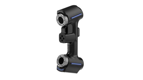
The INSVISION portfolio is deliberately split across these four task classes. AlphaScan serves as the primary portable option because most reverse engineering work in automotive, general manufacturing, and aftermarket spare parts involves components you can pick up, rotate, and scan from multiple angles without losing reference. Its portability removes the need to stage parts in a dedicated lab.
When the target grows beyond what one person can reposition, industrial 3D scanner becomes the logical step. When the tolerance band tightens to aerospace or medical levels, industrial 3D scanner provides the tracked reference network that handheld scanning alone cannot guarantee. And when the same part repeats in serial production, industrial 3D scanner removes operator drift from the equation.
For engineers evaluating a reverse engineer 3D scan workflow, the practical starting point is not a spec sheet comparison. It is a routing question: What is the largest dimension you must capture, what is the tightest tolerance you must hold, and how many times must you repeat the scan? Answer those three questions, and the correct INSVISION solution tends to select itself.
AlphaScan Handheld 3D Scanner: Fit for Automotive Component Reverse Engineering
What happens when a legacy powertrain casting fails and the original CAD model no longer exists? That is the question maintenance engineers and aftermarket suppliers face more often than many OEMs would like to admit. The part sits on a bench in the repair bay, the drawing is either missing or obsolete, and someone needs to produce a replacement or a modified version that fits the existing assembly.
Traditional manual measurement can capture a few critical dimensions, but complex cast surfaces, draft angles, mounting bosses, and internal port geometry resist calipers and height gauges. A handheld 3D scanner changes the workflow entirely. With the INSVISION AlphaScan, reverse engineer 3D scan work moves directly to the part rather than forcing the part onto a fixed measuring setup.
That shift matters when the casting weighs forty kilograms and the nearest metrology lab is across the plant.
The AlphaScan handheld form factor is well suited to shop-floor conditions. A legacy powertrain casting rarely sits in a clean, vibration-isolated inspection room. It sits on a pallet, a workbench, or a repair stand, surrounded by tooling and overhead cranes.
The scanner operates without a tripod-mounted fixed coordinate system, so the operator can walk around the part, capture the underside of flanges, scan into deep pockets, and reposition without losing alignment. Full-field capture means the system builds a dense point cloud across the entire visible surface in one continuous session. For reverse engineering, that completeness is the point.
You are not sampling a few dozen points; you are collecting the geometric definition of the casting as it actually exists, including wear, distortion, and previous repair modifications.
In a typical workflow, the operator first prepares the surface. Cast aluminum or iron responds well to a light developer spray if the surface is shiny or oily. Markers may be applied for alignment, though the AlphaScan’s geometry-based tracking reduces the need for dense marker fields on complex organic shapes. The scan itself progresses in overlapping passes.
The software registers each frame against the previous data, building the mesh in real time. Areas with deep recesses or hidden pockets may require additional passes at different angles, but the handheld approach allows the operator to react to what the screen shows rather than following a fixed scan plan.
The output mesh is not the final deliverable. It is the starting point for CAD reconstruction. Once the scan data is cleaned and decimated to a manageable size, the mesh exports to common industrial platforms through standard formats. Reverse engineering software can then build NURBS surfaces over the scanned geometry, or the mesh can serve as a reference for creating parametric solid models.
For a powertrain casting, the designer typically rebuilds the part around functional features such as bearing bores, sealing faces, and mounting interfaces, while using the scan data to define the organic surfaces and wall thicknesses that are difficult to model from scratch. The scanned mesh also supports CAM programming when the goal is direct machining of a replacement part or a pattern for recasting.
From a lean manufacturing perspective, this workflow reduces the iteration loop that plagues traditional reverse engineering. Instead of measuring, modeling, cutting a test piece, finding the mismatch, and repeating, the engineer starts with a dense geometric dataset that captures the actual part condition. That first CAD model is far more likely to match the physical part on the first try.
Less rework means fewer wasted setups, less scrap material, and shorter downtime for the vehicle or machine waiting on the replacement component. In an Industry 4.0 context, the scan data also becomes a digital asset. The mesh can be archived as a digital twin of the legacy part, available for future design changes, quality comparisons, or supplier communication.
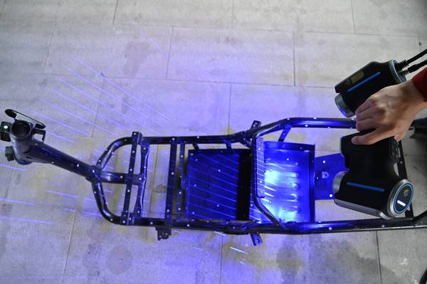
For Western manufacturers dealing with aging equipment fleets, the value extends beyond a single part. Once the scanning workflow is established, the same AlphaScan unit can support dimensional inspection on incoming castings, first-article verification on new supplier parts, and digital archiving of critical spares before they fail. The reverse engineer 3D scan capability is not a one-off rescue tool;
it becomes part of the plant’s broader data-driven maintenance and engineering strategy. The key is matching the tool to the part size and site constraints. Handheld full-field scanning fits the mid-size casting range well, where the part is too complex for manual layout but not large enough to justify a dedicated automated scanning cell.
Validation Workflow and Decision Checklist for Reverse Engineer 3D Scan Investments
Most teams evaluate a reverse engineer 3D scan purchase the wrong way. They fixate on scanner specs, compare software screenshots, and ask vendors for reference lists. Then they buy a system that struggles with the actual part geometry, site constraints, or CAD handoff requirements they face every week.
The better approach is to treat the evaluation like any other metrology investment: route the decision by part size, site freedom, marker conditions, takt time, and batch repeatability. That means running a controlled sample validation before committing, then scoring the results against a decision checklist that reflects your real reverse engineering workflow.
Start the validation with one representative test part. Do not pick a simple prismatic bracket. Choose a component with complex organic surfaces, tight fillets, deep pockets, or thin-wall transitions. If your team regularly reverse engineers castings, forgings, or injection-molded parts with freeform geometry, select a part that includes those features. The test part should also represent the size range you expect.
A scanner that works well on a 200 mm gear housing may fall apart on a 1.2 m intake manifold or a 40 mm medical device component. Define the deliverable requirements before scanning. Will you need a watertight mesh for downstream surfacing? Do you need reference dimensional markers tied to a known datum scheme? Does the output need to move cleanly into SolidWorks, NX, CATIA, or Geomagic Design X? Write those requirements down.
A scan that looks good in the vendor’s viewer but requires hours of cleanup in your CAD package is not a successful validation.
During the validation, compare the scanned output against the design specification or a calibrated reference model. Check deviation maps on critical features. Look at edge sharpness, hole roundness, and surface noise in low-reflectivity areas. If the part requires spray or marker application, measure how much time that adds per cycle.
This is where the INSVISION AlphaScan handheld scanner tends to show its value for reverse engineering work. It handles fine-grained surface capture without requiring heavy marker coverage on most geometries, which reduces setup time and minimizes post-processing cleanup.
The scanner’s output format compatibility with mainstream CAD and reverse engineering software also shortens the handoff from scan data to parametric or NURBS model.
After the sample validation, run the decision checklist. Score each option across five constraint dimensions: part size envelope, site freedom, marker tolerance, takt time per part, and batch repeatability.
For reverse engineering, batch repeatability matters less than it does in production inspection, but it still affects consistency when scanning multiple parts from the same family or re-scanning a worn component after modification. Add compliance criteria specific to your industry. Automotive OEM suppliers may need to meet customer-specific quality documentation requirements.
Aerospace MRO or engineering teams operating under AS9100 will need traceable scan records and controlled data handling. Medical device and energy sector teams often add material documentation and audit trail requirements. If the scanner vendor cannot demonstrate how the system supports these requirements, the validation is incomplete.
Post-purchase support access is the last checkpoint. Reverse engineering projects rarely follow a clean linear path. Your team will hit geometry that refuses to mesh cleanly, alignment problems on large parts, or software export issues. Ask the vendor how they handle application support after delivery. Can you send a scan file for review?
Is there access to application engineers who understand CAD surfacing, not just scanner operation? INSVISION’s support model includes practical application assistance for reverse engineering workflows, which matters more than a spec sheet once the system is on your floor.
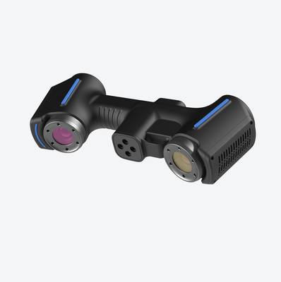
The conclusion is straightforward. Use case-based routing prevents bad scanner purchases. A structured validation with a representative part, defined deliverables, and a scored decision checklist gives you evidence instead of vendor claims. When the evaluation is tied to part geometry, site conditions, and CAD handoff requirements, the right reverse engineer 3D scan solution becomes obvious.
INSVISION’s AlphaScan fits teams that need flexible handheld capture, clean mesh output, and a practical path from scan data to usable CAD models, without the marketing noise that clouds most industrial scanner evaluations.
Hangzhou Insvision Technology Co., Ltd.
Address: Building 1, No. 1399 Liangmu Road, Yuhang District, Hangzhou, Zhejiang 311121, China
Copyright © Hangzhou Insvision Technology Co., Ltd. All rights reserved.
Copyright © Hangzhou Insvision Technology Co., Ltd. All rights reserved.