

Structured Light 3D Scanner Workflow From Scan Capture to Industrial Quality Reports
structured light 3d scanner: Shop-Floor Quality Pain Points Addressed by Structured Light 3D Scanning The key takeaway is simple: most shop-floor quality.
Shop-Floor Quality Pain Points Addressed by Structured Light 3D Scanning
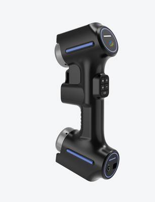
The key takeaway is simple: most shop-floor quality bottlenecks are not caused by a lack of measurement data. They are caused by data that arrives too late, covers too few features, or cannot be trusted by the next person in the process. A structured light 3D scanner changes that equation because it captures dense, dimensional information at the point of production, not days later in a lab.
Practical Workflow
- Shop-Floor Quality Pain Points Addressed by Structured Li… — The key takeaway is simple: most shop-floor quality bottlenecks are not caused by a lack of measurement data.
- Pre-Scan Station Setup and Cross-Team Preparation Protoco… — Most shops still assume a structured light 3D scanner is just another camera on a tripod.
- Scan Path Execution and Real-Time Data Validation Workflo… — A structured light 3D scanner earns its keep on the shop floor only when the scan path is treated as a controlled process step, n…
- Point Cloud Processing and Cross-Team Deviation Review — Most people assume the bottleneck in dimensional inspection is measurement speed.
Western discrete manufacturers face this problem in different forms. An automotive OEM running first-article inspection on a stamped bracket may wait hours for a CMM report that covers only a handful of pre-programmed points. An aerospace MRO team measuring a legacy turbine housing often has no CAD model at all, so conventional touch probing becomes guesswork.
Deployment Validation Checklist
| Focus Area | Decision Point | Deployment Note |
|---|---|---|
| Target part | Check size, surface condition, and key tolerances against the scan task | Run a full trial scan on a representative part |
| Data workflow | Verify point cloud, deviation map, and quality-report handoff | Confirm export formats and review ownership in advance |
| Shop-floor use | Review training, calibration, lighting, and working space | Keep the validation record as a repeatable inspection reference |
A medical device manufacturer verifying an implant’s freeform surface against a tight profile tolerance needs thousands of points to make a defensible pass/fail call. In each case, the inspection bottleneck is not the part. It is the gap between the measurement technology and the production workflow.
The common assumption is that structured light scanning belongs in a temperature-controlled metrology lab. That view is outdated. Modern structured light 3D scanners are built for the floor: they tolerate ambient vibration, handle varying surface finishes, and produce repeatable data quickly enough for an operator to act on the result before the next part enters the station.
The technology does not replace a CMM for every task, but it closes a specific gap: dense, fast, full-field measurement where legacy tools are too slow or too sparse.
From a quality and process collaboration standpoint, the structured light workflow creates a standardized handoff. The operator scans the part, the software aligns the point cloud to the CAD nominal or to a reference scan, and the deviation map shows exactly where the part is out of tolerance. That deviation map becomes the common language between production, quality, and engineering.
Instead of debating whether a single probed point was representative, the team reviews the same color-mapped surface. Exceptions are visible. GD&T callouts such as profile, flatness, and runout can be evaluated against the full dataset, not a sparse sample.
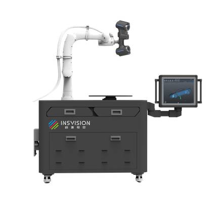
This matters for lean manufacturing because the goal is not more inspection. The goal is earlier, faster, and more actionable inspection. A structured light 3D scanner shortens the loop between part production and dimensional feedback. For first-article inspection, that means fewer bottlenecks at the CMM. For MRO legacy parts, it means capturing geometry that has no CAD reference.
For medical implants, it means verifying complex freeform tolerances with enough data density to support a documented pass/fail decision. The technology fits into existing quality workflows because it produces the same type of deliverable inspection teams already use: a dimensional report, a deviation map, and a traceable dataset. The difference is speed and coverage.
INSVISION industrial 3D scanners are positioned for exactly this type of shop-floor use. The intent is not to replace the CMM or the profilometer. It is to put a fast, full-field measurement capability at the station where the part is made or repaired.
When a quality engineer can see a color map of surface deviation before the part leaves the cell, the conversation shifts from “is this part good?” to “what do we adjust next?” That is the point where measurement starts supporting process control instead of just sorting scrap.
Pre-Scan Station Setup and Cross-Team Preparation Protocols
Most shops still assume a structured light 3D scanner is just another camera on a tripod. That assumption falls apart the moment someone scans a machined shaft with a light oil film and wonders why the point cloud looks noisy.
Pre-scan setup matters more than the scanner itself. For structured light, the real work happens before capture. Parts should be fixtured so the projected pattern wraps the surfaces you actually care about, not just the surfaces that are easy to reach. Reflective, dark, or translucent parts need surface preparation. In many cases, a thin developer spray or matting powder is enough.
In others, you need to mask polished flanges or bearing journals where spray would interfere with downstream assembly.
Environment matters too. Ambient sunlight or overhead halogens can wash out the projected fringe pattern. Vibration from nearby presses or conveyors creates ghosting. The station should sit away from direct light and isolated from floor vibration. INSVISION structured light 3D scanners are built for shop-floor use, but they still need a stable, controlled capture zone.
Boundary conditions are straightforward. Very small parts with fine internal geometry may not suit structured light. Large weldments are fine, but scan time goes up. Glossy chrome, clear acrylic, or near-mirror finishes will fight you unless you prepare the surface.
Quality technicians own station setup. Process engineers own scan criteria. Before scanning starts, both should sign off on a short checklist: fixture stability, surface condition, ambient light level, part temperature, and expected GD&T callouts. That handoff prevents bad data from entering the inspection workflow and keeps everyone aligned on what the scan is supposed to prove.
Scan Path Execution and Real-Time Data Validation Workflows
A structured light 3D scanner earns its keep on the shop floor only when the scan path is treated as a controlled process step, not a technician’s improvisation. The workflow difference shows up quickly: pre-approved paths reduce variation, while ad-hoc scanning creates inconsistent coverage and downstream rework.
For complex geometries such as turbine airfoils, automotive interior trim, or medical device components, scan path planning starts with identifying critical features that must appear in the point cloud. Technicians then execute those pre-approved paths using the INSVISION structured light 3D scanner, which projects sequential fringe patterns and captures full-field data through stereo camera triangulation.
Real-time completeness checks happen at the station. The technician verifies that every designated surface patch returned sufficient data density before the part moves.
When undercuts or hard-to-capture areas show gaps, the exception protocol matters. The technician flags the region, and a process engineer reviews whether an adjusted scan path is warranted. This role separation keeps execution fast while ensuring data quality decisions rest with someone who understands downstream inspection requirements. Parts do not exit the scan station with unresolved gaps.
That discipline is what actually shortens lean cycle time.
Point Cloud Processing and Cross-Team Deviation Review
Most people assume the bottleneck in dimensional inspection is measurement speed. In practice, the real friction shows up after data capture, when quality and process engineering try to reconcile deviation data that neither team fully trusts. A structured light 3D scanner changes that handoff because it produces a full-field point cloud rather than a sparse set of touch-probe coordinates.
The quality team can clean and filter the scan, align it to the CAD reference model, extract GD&T callouts, and generate a complete deviation map in one workflow. Process engineering reviews the same map to spot patterns, tool wear, clamping distortion, or thermal drift, instead of guessing from a handful of discrete points. With traditional CMM workflows, unflagged surface areas between probed points become blind spots.
That forces repeated setup, re-measurement, and back-and-forth clarification. INSVISION structured light 3D scanners deliver dense surface data that both teams can interrogate independently, reducing those loops. The same scan data also supports reverse engineering of legacy parts for aerospace and energy MRO work, where CAD models are often outdated or missing entirely.
Quality Report Delivery and Structured Reinspection Triggers
When a first-article inspection closes, the real work often starts in the documentation handoff. Aerospace buyers expect AS9102 forms with ballooned drawings and measured values tied to each characteristic. Automotive suppliers live inside PPAP packages where dimensional results must align with control plans. Medical device teams need FDA-aligned records that survive audit scrutiny years after shipment.
A structured light 3D scanner changes how that package comes together.
Instead of manually transcribing CMM readouts or height-gage values into spreadsheets, the scan dataset becomes the source record. Color-mapped deviation plots, pass-fail callouts against GD&T tolerances, and raw point cloud files can be exported together.
INSVISION structured light 3D scanners output industry-standard formats that drop directly into common quality management and CAD software, so quality engineers, process owners, and design teams work from the same dataset without re-entering numbers.
Reinspection triggers should be defined before production starts, not discovered after a non-conformance. Tooling changeovers, process parameter adjustments, and batch rejection events are the classic conditions. When a mold insert is replaced, a fixture is reworked, or a CNC program is edited, the affected characteristics need fresh dimensional verification.
Historical structured light datasets make that comparison straightforward: scan the new condition, overlay it on the archived baseline, and isolate exactly which features shifted.
Those archived datasets also feed continuous improvement work. A quality manager investigating recurring drift on a bore position can pull scan data from the last six production runs and correlate dimensional movement with tool wear or ambient temperature changes. That is the Industry 4.0 digital thread in practice—not a dashboard concept, but a searchable measurement history that supports root cause analysis.
INSVISION structured light 3D scanners support this workflow by producing repeatable, archivable datasets that remain usable as inspection standards evolve.
Common Structured Light 3D Scanning FAQs for Industrial Teams
The answers below assume a basic understanding of how structured light scanning works and where it fits in a dimensional inspection workflow. If you are still evaluating the technology category, review the principle and workflow sections first.
What is the difference between structured light 3D scanning and laser 3D scanning?
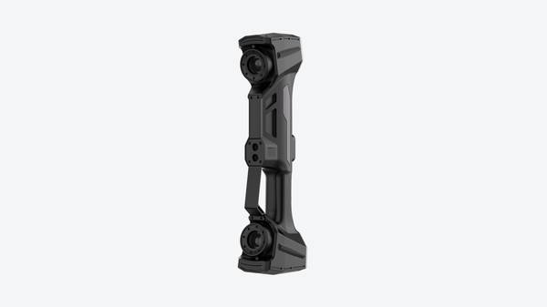
Both capture point cloud data, but the acquisition method differs. A structured light 3D scanner projects a known light pattern across a surface and derives geometry from how the pattern deforms. Laser scanning moves a single line or point across the part. In practice, structured light tends to cover larger areas in one frame and works well on stationary parts in controlled lighting.
Laser scanning often handles darker or more variable surface conditions better. Neither is universally superior. The right choice depends on part size, surface finish, cycle time, and whether the scanner sits in a lab or next to a machining cell.
Can structured light scanners capture highly reflective or transparent industrial parts?
Not without preparation. Shiny machined surfaces, polished tooling, and clear plastics scatter or transmit light in ways that break the pattern-to-point calculation. The standard approach is to apply a fine, removable matting spray. This changes the surface condition temporarily and allows reliable data capture. Some teams also adjust exposure or use polarization, but spray remains the most predictable fix on a shop floor.
If the part cannot be coated, or if coating changes the measured surface beyond tolerance, that is a boundary condition to flag during evaluation.
How does structured light 3D scanning support ISO/ASME GD&T compliance?
The scanner produces dense point data, not a GD&T report by itself. The compliance path runs through the inspection software. After alignment and meshing, the software extracts features and evaluates them against the drawing callouts: position, profile, runout, flatness, and so on. The scanner’s job is to deliver enough point density and repeatability for the software to make those calculations defensibly.
Teams should verify the combined system against a certified artifact and document the measurement uncertainty before relying on it for first-article or in-process sign-off.
What factors should teams evaluate when assessing structured light 3D scanning for their shop floor?
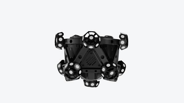
Start with the part: size, surface finish, and required tolerances. Then look at the environment: vibration, ambient light, temperature drift. After that, evaluate the data deliverable. Does quality need a color map, a full mesh, a CAD comparison, or a simple pass/fail? Cycle time matters only after these are defined. Finally, check how the scanner fits the station workflow. Who runs it? Where does the data go?
Who reviews exceptions? For teams evaluating INSVISION industrial 3D scanner options, the same questions apply before any specification review.
Hangzhou Insvision Technology Co., Ltd.
Address: Building 1, No. 1399 Liangmu Road, Yuhang District, Hangzhou, Zhejiang 311121, China
Copyright © Hangzhou Insvision Technology Co., Ltd. All rights reserved.
Copyright © Hangzhou Insvision Technology Co., Ltd. All rights reserved.