

What Optical Measuring Machine Validation Actually Entails in Factory Quality Workflows
Meta description: A practical guide to validating and integrating optical measuring machines into industrial quality workflows, covering sample testing.
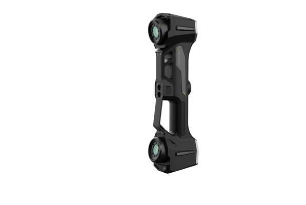
A new optical measuring machine often arrives with a simple expectation: install it in an inspection cell and let it start earning its keep. The more realistic path is different. In many automotive OEM, aerospace MRO, medical device, and energy operations, the gap between specification and daily performance comes from boundary conditions, not from hardware accuracy. The measuring volume may not match the largest part envelope.
Vibration, lighting, or thermal drift may not be controlled. Measurement data may not enter existing FAI, PPAP, or MRO documentation without manual rework.
This article explains what validation and integration actually require when an optical measuring machine moves into factory quality workflows. It covers pre-deployment sample testing, environmental limits, data alignment, operator readiness, and the conditions that make large-format optical inspection repeatable.
What an Optical Measuring Machine Does in a Quality Loop
An optical measuring machine captures dimensional information without contact. Depending on the measurement principle, it may project structured light, scan with laser lines, or use photogrammetry to reconstruct part geometry. The output is a point cloud or mesh that quality engineers compare against CAD nominals or reference geometry.
Key Points at a Glance
- An optical measuring machine captures dimensional information without contact.
- Before committing an optical measuring machine to a production line, quality teams should verify the conditions that affect repeatability and me…
- Sample validation answers a practical question: will the optical measuring machine resolve the GD&T callouts that inspectors currently struggle…
- An optical measuring machine succeeds in production when it becomes a new inspection checkpoint, not a standalone lab instrument.
The practical value in production is not the point cloud alone. It is the ability to produce deviation maps, confirm GD&T callouts, and route pass/fail information into the plant’s quality system. That is why the machine’s physical installation matters less than how its data connects to existing inspection gates.
Boundary Conditions That Determine Deployment Success
Before committing an optical measuring machine to a production line, quality teams should verify the conditions that affect repeatability and measurement validity.
| Deployment variable | What to verify before rollout |
|---|---|
| Measurement volume | Largest part envelope, orientation, and fixture access |
| Surface condition | Painted, machined, composite, reflective, or semi-translucent surfaces |
| Environmental stability | Vibration, ambient light, air movement, and thermal drift |
| Datum structure | Shared CAD datum and alignment logic with existing inspection methods |
| Data deliverable | Mesh file, deviation map, GD&T report, and QMS-compatible output |
| Operator workflow | Setup time, routine repeatability, and error detection before data release |
Misalignment in any of these areas can turn a capable measuring system into an underutilized lab tool. The most common failure is assuming that all optical tools handle large-format parts equally well. Large-format inspection is a specific engineering condition.
It requires a scanner with sufficient volume coverage, but also a deployment plan that addresses part access, surface preparation, and data density across large curved surfaces.
Pre-Deployment Sample Validation
Sample validation answers a practical question: will the optical measuring machine resolve the GD&T callouts that inspectors currently struggle to verify?
Under an ISO 17025-aligned quality management approach, the process starts with critical inspection characteristics from the production drawing. Those may include surface profile tolerances, position callouts, runout, and other ASME Y14.5 requirements. The next step is to test representative sample parts.
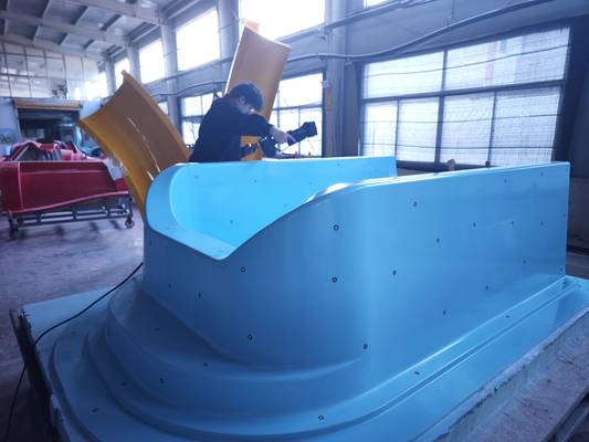
This validation checks scan coverage, repeatability on tight features, and whether the captured data density is sufficient for the required tolerance band. For large or complex workpieces, INSVISION’s AlphaVista sample validation service uses a large-format handheld 3D scanner on painted automotive panels, composite aerospace components, and similar surfaces where finish, curvature, and access can affect results.
The report from that exercise identifies two outcomes: where the system fits the inspection workflow, and where additional fixture control or surface preparation may be needed.
On-Site Integration as Process Integration
An optical measuring machine succeeds in production when it becomes a new inspection checkpoint, not a standalone lab instrument. The integration sequence should begin with workflow mapping. The team identifies where dimensional data is already required, whether at incoming goods, in-process assembly, or final inspection. The system then sits inside those existing gates.
Workspace planning follows 5S principles. The scanner, reference artifacts, and cabling receive fixed locations. Temporary setups are marked clearly. Calibration is linked to the plant’s current quality system schedule, so the new device inherits the same audit trail instead of creating a parallel process.
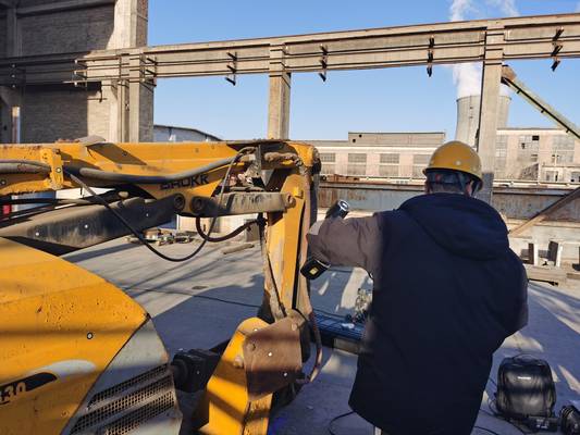
Portability changes the integration model for large parts. INSVISION’s AlphaVista can move between work cells for fixed gauging and ad-hoc large-part inspection, such as wind turbine sections, fuselage segments, or body-in-white assemblies. The part stays in place, and the measuring system travels to the work area.
Data and Report Alignment
For Western quality teams, measurement data is a deliverable. When an optical measuring machine replaces manual inspection on large parts, the first concern is often not scanner accuracy. It is whether the output moves into existing FAI, PPAP, or MRO documentation without a rework step.
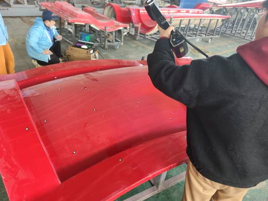
A usable inspection package typically includes mesh files, deviation color maps tied to CAD nominals, and GD&T inspection reports with pass/fail callouts. INSVISION’s AlphaVista outputs are formatted for common CAD platforms and QMS packages, allowing engineers to import results directly instead of reformatting point clouds.
For large assemblies, scan data can be aligned to the CAD reference model before deviation analysis. That keeps the report logic consistent with the drawing. Datum alignment is where mixed-software workflows often break down.
If the optical measuring machine and the existing quality system do not share a common datum structure, the inspection data may not support a PPAP submission, an MRO repair file, or a customer audit without manual translation.
Operator Training and Post-Implementation Reviews
More plants are moving dimensional inspection out of isolated lab spaces and into process-control loops. That shift makes operator training and post-install audits central to whether an optical measuring machine pays off.
Training should be divided by role. Quality technicians need routine scan operation: part setup, fixture referencing, running established programs, and catching gross errors before data moves downstream. Senior quality engineers and process engineers need advanced dimensional analysis, GD&T interpretation, first-article reporting, and an understanding of how measurement results feed process correction.
Hands-on work should use the facility’s own parts so sessions match real drawings and control plans rather than generic sample blocks.
Post-implementation reviews assess tool utilization, inspection throughput, and alignment with quality goals. If the review finds duplicate records or waiting on offline analysis, the workflow needs adjustment. This matches kaizen and ISO 9001 corrective action loops, where measurement capability remains under periodic review as part of process control.
Where Optical Measuring Fits and Where It Does Not
Optical measuring machines are strong choices when the inspection task involves large, contoured, or difficult-to-reach surfaces. They capture dense point clouds quickly and provide fast visual deviation mapping. They are less appropriate when the inspection task demands contact probing of deep internal features, when part surfaces are not optically cooperative, or when the plant cannot control vibration and thermal drift.
A contact CMM may still be preferable for certain prismatic features or tight geometric tolerances on machined surfaces. The two methods can coexist. The decision should be driven by part geometry, tolerance band, access, and the required data deliverable.
Scaling Reuse Across Factory Operations
A plant often starts with an optical measuring machine on one line or inspection cell. That first use proves capability. The larger return comes from moving the same tool to other tasks. The condition that matters is workflow alignment: scan data, reporting, and operator steps should fit existing quality routines, not create a separate measurement silo.
Portable large-format systems widen reuse. Teams can carry the same unit to NPI prototype inspections, supplier quality audits, and cross-facility benchmarking. This reduces part transport, duplicate gauging, and waiting, supporting lean waste reduction.
INSVISION’s AlphaVista matches this pattern because its large-format capture and portability support use across multiple production lines, MRO bays, and off-site supplier locations. For teams evaluating rollout, the sequence should be structured: define the data deliverable, train operators on that output, and expand to reuse tasks after the routine is stable.
Common Misconceptions and Technical Questions
Does a high-accuracy specification guarantee good inspection results?
No. Accuracy is only one variable. Datum alignment, surface preparation, environmental stability, and report integration all determine whether the optical measuring machine produces usable pass/fail data.
Can one optical measuring machine handle all large-format parts?
No. Measurement volume, standoff distance, surface finish, and access conditions vary. A large-format handheld 3D scanner works well on painted panels and composite surfaces, but reflective or semi-translucent materials may still require surface preparation or alternative measurement modes.
Is sample validation necessary if the drawing tolerances are within the machine’s specification?
Yes. Sample validation tests the complete measurement chain: part access, fixture repeatability, data density, and output logic. A specification sheet does not confirm that the system will work inside the plant’s actual inspection gate.
Summary
Deploying an optical measuring machine in a factory quality workflow is not a hardware installation project. It is a process integration task. The teams that get the most value define the data deliverable before installation, validate the technology on real parts, align reporting with existing CAD and QMS systems, and train operators for the specific inspection routines they will run.
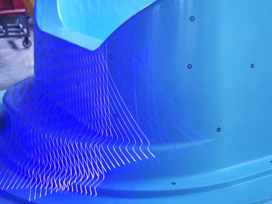
The goal is not to add a new measurement device. It is to shorten dimensional feedback loops, reduce first-article inspection bottlenecks, and create a repeatable data path from part surface to quality record. When that path is clear, an optical measuring machine can move beyond a single inspection cell and become a shared factory resource across lines, supplier audits, and MRO workflows.
Hangzhou Insvision Technology Co., Ltd.
Address: Building 1, No. 1399 Liangmu Road, Yuhang District, Hangzhou, Zhejiang 311121, China
Copyright © Hangzhou Insvision Technology Co., Ltd. All rights reserved.
Copyright © Hangzhou Insvision Technology Co., Ltd. All rights reserved.