

STL File Definition, Core Principles, Parameters, and Industrial Use Boundaries
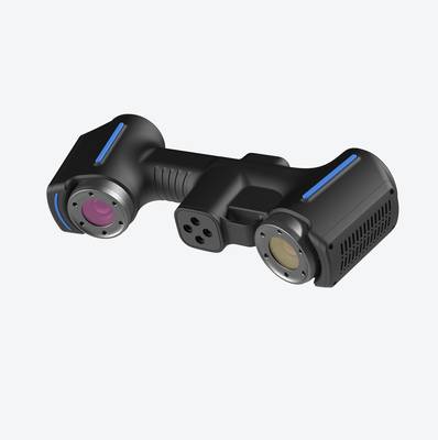
Meta Description: The STL file is a tessellated surface format used widely in industrial 3D printing, 3D scanning, and mesh-based inspection.
Definition and Industrial Context
An STL file is a tessellated surface representation of 3D geometry derived from stereolithography. 3D Systems introduced the format in the late 1980s for additive manufacturing equipment, and it became an early de facto standard for moving part geometry into rapid prototyping machines.
In contemporary industrial workflows, it remains a neutral geometry carrier for 3D printing, polygon-based inspection, and lightweight model sharing.
Practical Workflow
- Definition and Industrial Context — An STL file is a tessellated surface representation of 3D geometry derived from stereolithography.
- Core Working Principles — An STL file describes surface geometry as a mesh of triangular facets.
- Key Technical Parameters for Evaluation — STL file evaluation uses measurable mesh parameters to judge suitability for downstream work.
- Industrial Use Boundaries — An STL file is a tessellated surface representation, not parametric CAD.
The file structure stores only surface geometry as a mesh of triangular facets. Each facet is defined by three vertices and a unit normal vector, describing a closed or open surface shell. STL contains no native support for color, texture, material properties, GD&T callouts, or parametric feature history. That limitation is often acceptable for prototyping and scanning reference data, but it removes design intelligence.
Western automotive and aerospace organizations adopted STL early for first-article prototyping, wind-tunnel model fabrication, and fit-form verification because the format was simple, machine-readable, and already supported by stereolithography equipment.
| Data element | STL file support |
|---|---|
| Surface mesh facets | Yes |
| Facet normal orientation | Yes |
| Color or texture | No native support |
| Parametric features / history | No |
| GD&T, material, tolerance metadata | No |
Core Working Principles
An STL file describes surface geometry as a mesh of triangular facets. Each facet stores a unit normal vector and three vertex coordinates. The normal indicates the outward-facing side of the triangle; vertex ordering follows the right-hand rule, and coordinates are expressed in the source CAD or scan reference frame. STL does not explicitly carry units, datum references, GD&T callouts, or feature history.
Curved surfaces are approximated by tessellation. Export settings such as chordal deviation and angular tolerance control how many triangles replace a curved surface. Tighter tolerances yield smaller facets, larger files, and better approximation of radii or airfoil profiles. In scan data processing, software meshes point clouds and decimates the resulting triangles into this faceted format.
Additive manufacturing slicing tools then intersect the triangles with layer planes. Reversed normals, duplicate facets, or holes create open contours and failed toolpaths.
Production uses two encoding variants:
| Encoding | Structure | File size | Processing behavior |
|---|---|---|---|
| ASCII | Text-based facet normal and vertex lines | Larger | Human-readable, slower parsing |
| Binary | Fixed-length facet records | Compact | Faster parsing, typical for production transfer |
Key Technical Parameters for Evaluation
STL file evaluation uses measurable mesh parameters to judge suitability for downstream work. The five parameters below align with ISO/ASTM 52900 terminology and common aerospace MRO, medical device prototyping, automotive tooling validation, and energy component inspection workflows.
| Parameter | Technical Definition | Industrial Relevance |
|---|---|---|
| Facet count | Total number of triangular elements in the tessellated surface. | Controls polygon budget; high counts preserve curvature in aerospace MRO part reverse engineering but can burden toolpath generation in automotive tooling validation. |
| Mesh resolution | Local triangle size and chordal deviation from the nominal surface. | Determines small feature capture for medical device prototyping; coarse resolution can miss GD&T callouts on thin walls or small radii. |
| Watertightness | Closed manifold surface with no gaps, non-manifold edges, or inverted normals. | Needed for build preparation and volume inspection; aerospace MRO and energy component inspection commonly reject non-watertight files before CFD or NDT simulation. |
| Encoding type | Binary or ASCII representation of vertex and facet data. | Binary reduces file size and parse time for large industrial scans; ASCII supports manual QA but is inefficient for production data exchange. |
| File size | Total byte count after encoding. | Affects transfer, archive, and software memory; automotive tooling validation should justify size by tolerance-driven mesh resolution, not redundant tessellation. |
Industrial Use Boundaries
An STL file is a tessellated surface representation, not parametric CAD. Engineering and quality teams should treat it as a mesh interchange format with defined boundaries. In Western OEM and contract manufacturing, STL fits digital thread points where surface geometry is needed without parametric history or semantic GD&T.
| Industrial application | Where STL fits | Boundary condition |
|---|---|---|
| Additive manufacturing prototyping | Build prep and slicing input | Watertight mesh; units and chordal tolerance documented |
| 3D scan data export for dimensional inspection | Surface deviation color maps | Does not carry GD&T callouts or datum constraints |
| Reverse engineering of legacy parts | Scan seed geometry | Requires NURBS/parametric reconstruction before design reuse |
| Tooling design support | Clearance, fit, and setup reference | Not a substitute for machined feature tolerances |
| Digital twin surface geometry input | Lightweight visualization mesh | Lacks PMI and feature semantics for model-based definition |
Under lean manufacturing, STL remains a lightweight geometry carrier between scanning, additive manufacturing, and visualization. Authoritative design data stays in CAD/PLM. ISO 17296-4 situates STL as AM build-prep mesh data, not a design-authority dataset. That avoids mesh-to-solid conversion rework.
Common Misconceptions in Industrial STL Use
The STL file is a tessellated surface representation, not a product definition dataset. A common assumption is that an STL file carries dimensional tolerance metadata. It does not. ASME Y14.5 GD&T callouts are feature-based annotations tied to nominal geometry; an STL contains only triangle vertex coordinates and face normals.
Treating an STL as the inspection authority therefore drops the datum reference frame, modifiers, and feature-control frames needed for first-article inspection.
Another assumption is that STL is the only format accepted by industrial 3D printers. In practice, AMF and 3MF were defined partly to carry units, materials, build data, and other metadata that STL lacks. STL remains common, but it is not a technological requirement.
| Misconception | Technical reality |
|---|---|
| STL natively holds tolerance metadata | STL stores mesh topology/geometry only; no GD&T, PMI, or units |
| Higher facet count always improves functional performance | Facet count affects surface approximation only; it does not change material properties, process capability, or GD&T outcomes |
| STL cannot be used in high-tolerance inspection | STL can support surface-deviation and mesh comparison workflows, but feature tolerances still require a controlled CAD/PMI source |
For high-tolerance workflows, STL is not useless. Mesh-to-CAD comparisons can locate surface deviation quickly. But tolerance acceptance per ASME standards remains a feature and datum problem, not a triangle-density problem.
Related 3D File Formats and Industrial Compatibility
An STL file describes surface geometry as a triangular mesh. It does not carry parametric feature history, GD&T callouts, or product manufacturing information. In industrial workflows, STEP, IGES, and 3MF are often exchanged alongside STL because each serves a different engineering purpose.
STEP (ISO 10303) is used for parametric solid models and assemblies. AP242 editions can retain GD&T and other model-based definition data, making STEP suited to CAD-to-CAD exchange, CNC programming, and design change processes in automotive and aerospace programs. IGES remains present in legacy CAD exchange and long-life aerospace MRO archives.
It represents surfaces and curves rather than parametric design intent, so imported geometry frequently requires repair before editing. 3MF was designed for additive manufacturing. It combines mesh geometry with build metadata such as materials, colors, units, and support settings, reducing ambiguity that plain STL files can introduce.
| Format | Primary geometry type | Typical industrial use | Common compatibility |
|---|---|---|---|
| STL file | Triangular mesh | 3D printing, 3D scanning, polygon-based inspection | AM machines, 3D scanners, CAI software |
| STEP | Parametric solids/surfaces | CAD exchange, MBD, CNC programming | CAD/PLM, CAM, CMM software |
| IGES | Surfaces/curves | Legacy CAD archives, MRO, tooling | Older CAD/CAM and repair tools |
| 3MF | Mesh plus metadata | Additive manufacturing with multiple materials | AM build prep and production systems |
A scanned STL mesh often needs reverse engineering into STEP before parametric design changes can be applied. Format choice depends on whether the downstream task requires surface geometry, parametric history, or build-level manufacturing data.
Integration with Industrial 3D Scanning Workflows
STL files function as the standard exchange format for triangulated surface data produced by industrial 3D scanning systems. In dimensional inspection, reverse engineering, and quality control, the format’s main strength is interoperability. A scan exported as an STL can move into inspection software, CAD comparison tools, and mesh editing packages without proprietary translation steps.
| Workflow stage | STL file role | Typical downstream operation |
|---|---|---|
| Scan acquisition | Stores measured surface data as a triangulated mesh | Mesh cleanup, hole filling, alignment |
| Dimensional inspection | Provides reference surface for deviation mapping | CAD-to-mesh comparison, GD&T callout checks |
| Reverse engineering | Preserves as-built geometry for surfacing | Decimation, NURBS reconstruction, solid modeling |
| Quality control | Enables archival and repeat measurement overlays | First-article inspection, trend review |
Mesh density and watertightness remain practical limits. A coarse STL can hide edge breaks or local surface deviation during inspection. A dense STL may require decimation before reverse engineering workflows.
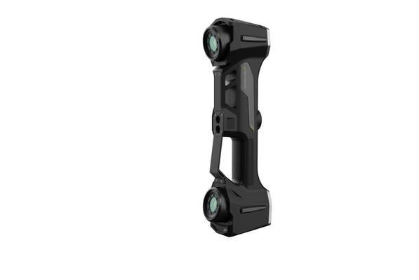
INSVISION supports STL file export as standard output on its industrial 3D scanning systems. That matters where automotive OEM, aerospace MRO, and medical device production environments already rely on STL-based mesh inspection and CAD rebuild workflows.
Frequently Asked Questions
An STL file is a faceted surface representation. It stores triangle vertices and facet normals, not feature definitions, units, or inspection datums. Most practical questions in industrial use come from that limitation.
1. Are STL files compliant with ISO standards for additive manufacturing?
ISO/ASTM 52900 defines terminology for additive manufacturing, but it does not name STL as a required format. STL remains common because most AM build-prep software accepts it. A more complete data exchange can be handled with ISO/ASTM 52915 AMF, which adds material, lattice, color, and unit information.
In a controlled production environment, the requirement is process-based: the STL must be generated with defined tessellation settings, checked for mesh defects, and compared to the nominal CAD model before release. If deviation exceeds the agreed tolerance, the STL is not fit for that downstream operation.
2. How can teams verify STL mesh quality before production or inspection?
Mesh verification should cover more than visual appearance.
- Watertightness: no open boundaries or missing triangles.
- Manifold edges: each edge shared by no more than two triangles.
- Normals: all face normals point outward consistently.
- Scale and units: the file is in the intended unit system.
- Tessellation deviation: chordal and angular tolerances match the part tolerance class.
These checks catch most failures that later appear as slicing errors, reversed surfaces, or false deviations in scan-to-CAD reports.
3. What is the difference between ASCII and binary STL for industrial applications?
Binary and ASCII STL files carry the same geometry, but they differ in size, speed, and practical use.
| Attribute | ASCII STL | Binary STL |
|---|---|---|
| Readability | Human-readable text | Machine-readable |
| File size | Several times larger | Compact |
| Parsing speed | Slower | Faster |
| Typical industrial use | Debugging small files, quick manual review | Production handoff, large surface meshes |
For industrial AM and metrology workflows, binary STL is the standard choice unless a specific text-based review step requires ASCII.
4. Can STL files be used for high-tolerance dimensional inspection?
STL can support color-map deviation displays and rough scan-to-CAD comparisons, but it is not an inspection master for high-tolerance dimensional control. A triangle mesh approximates curved surfaces, so bore positions, datum planes, and GD&T callouts are not explicitly represented.
For tight tolerances, acceptance data should reference native CAD or STEP geometry and be reported through a feature-based inspection format such as QIF or ASME Y14.45. STL may still appear as an intermediate scan mesh, but final dimensional acceptance should be tied to the nominal model, not the tessellated copy.
That boundary also appears in INSVISION’s technical approach to 3D digital workflows: STL is treated as transport geometry, not an inspection master.
Key Takeaways for Engineering and Quality Teams
An STL file stores surface geometry as a triangular mesh only. It does not carry units, GD&T callouts, material specifications, or PMI. That limitation sets the boundary for industrial use. In additive manufacturing and 3D scanning handoffs, STL remains the common interchange format across automotive OEM, aerospace MRO, medical device, and energy maintenance workflows.
| Evaluation parameter | Engineering check | Common pitfall |
|---|---|---|
| Mesh integrity | Watertight surface, no non-manifold edges, correct normals | Accepting holes, duplicate facets, or inverted triangles |
| Tessellation tolerance | Chord height, angular deviation, and facet size vs. part tolerance | Coarse export on curved features |
| Units and scale | Confirm mm/inch before import | Wrong scale after import; STL has no units |
| Geometry scope | Surface mesh only; no GD&T, PMI, or material data | Treating STL as a CAD or inspection master |
STL persists because it is simple and widely interoperable in global additive and 3D scanning ecosystems. Quality teams should control it as an engineering deliverable: validate the mesh, lock coordinate systems, and add CAD or PMI data before first-article inspection or machining.
- What Is 3D Scanning? Principles, Workflow, and Industrial Applications 3D scanning is a digital measurement technology that converts the surface geometry of physical objects into 3D data. This entry covers its working principles, core parameters, industrial use cases, common misconceptions, and related technical…
- What Is a 3D Scanner? Types, Parameters, and Selection Criteria A 3D scanner captures three-dimensional surface data from physical objects and converts geometry, dimensions, and features into digital data for inspection, reverse engineering, and modeling.
- What Is 3D Scanning Accuracy? Accuracy, Repeatability, and Resolution Explained 3D scanning accuracy describes how closely scan data matches an object's actual geometry and dimensions. It is assessed through local accuracy, volumetric accuracy, stitching accuracy, repeatability, and resolution.
- What Is Point Cloud Data? Point Clouds, Meshes, and CAD Models in 3D Scanning Point cloud data is an important raw data format in 3D scanning. It consists of discrete 3D coordinate points that describe object surface geometry and support inspection, reverse engineering, modeling, and archiving.
Hangzhou Insvision Technology Co., Ltd.
Address: Building 1, No. 1399 Liangmu Road, Yuhang District, Hangzhou, Zhejiang 311121, China
Copyright © Hangzhou Insvision Technology Co., Ltd. All rights reserved.
Copyright © Hangzhou Insvision Technology Co., Ltd. All rights reserved.