

What Industrial 3D Scanning Actually Does and Where It Fits in Modern Manufacturing
Metrology and quality teams across automotive, aerospace, medical device, and energy sectors are shifting from asking “Can we scan this part?
What Industrial 3D Scanning Is — and How It Works
At its simplest, industrial 3D scanning captures the surface geometry of a physical object and converts it into a dense digital point cloud, a mesh, or a parametric CAD model. The sensor projects structured light, laser lines, or a pattern onto the part, and cameras record the deformation of that pattern to triangulate millions of points per second.
The result is a digital twin that can be compared against nominal CAD, analyzed for GD&T callouts, or used to rebuild a part for which no drawing exists.
Practical Workflow
- What Industrial 3D Scanning Is — and How It Works — At its simplest, industrial 3D scanning captures the surface geometry of a physical object and converts it into a dense digital p…
- Key Technical Dimensions That Shape a Usable Scan — When teams move from a demo to a production line, five constraints usually dominate the conversation:
- How 3D Scanning Compares with Traditional Metrology — A common question is whether 3D scanning replaces a coordinate measuring machine (CMM).
- How to Evaluate a 3D Scanning Solution Without Relying on… — A reliable validation process starts with a representative production part — not an idealized test coupon.
What separates an industrial‑grade scan from a consumer‑grade mesh is not just resolution. It is metrological traceability, repeatability under varying temperatures and ambient light, and the ability to deliver a data set that a CMM operator or a quality engineer can trust without hours of cleanup.
Deployment Validation Checklist
| Focus Area | Decision Point | Deployment Note |
|---|---|---|
| Target part | Check size, surface condition, and key tolerances against the scan task | Run a full trial scan on a representative part |
| Data workflow | Verify point cloud, deviation map, and quality-report handoff | Confirm export formats and review ownership in advance |
| Shop-floor use | Review training, calibration, lighting, and working space | Keep the validation record as a repeatable inspection reference |
Systems built for the shop floor must also handle reflective, dark, or translucent surfaces — common in as‑cast, forged, or injection‑molded parts — without requiring the operator to spray every surface with developer.
Key Technical Dimensions That Shape a Usable Scan
When teams move from a demo to a production line, five constraints usually dominate the conversation:
- Part size and geometric complexity. Handheld scanners cover small to medium components with fine detail; large‑format systems capture full vehicle frames or tooling without stitching dozens of scans. A scanner that works beautifully on a 200 mm bracket may struggle on a 2 m weldment.
- Surface finish and material. Shiny, machined surfaces, black polymers, and transparent materials can scatter or absorb the projected pattern. The robustness of the scanner’s exposure control and algorithm determines whether you get a clean point cloud or a noisy one.
- Ambient lighting and shop floor stability. Strong overhead lighting, direct sunlight through a bay door, or vibration from nearby stamping presses can degrade structured‑light scans. Tracking‑based and automated systems differ in their immunity to these environmental factors.
- Required data deliverables. A watertight mesh for 3D printing has different accuracy requirements than a full GD&T deviation map with traceable reports. Teams must define early whether the output feeds a statistical process control system, a reverse‑engineering CAD package, or an audit trail for regulatory compliance.
- Operator skill and cycle time. Manual scanning can introduce shift‑to‑shift variability. Automated or semi‑automated systems that remove hand‑held positioning and trigger decisions produce consistent data at a predictable takt, which matters for high‑volume production or regulated industries.
How 3D Scanning Compares with Traditional Metrology
A common question is whether 3D scanning replaces a coordinate measuring machine (CMM). The answer is rarely a straight yes or no. CMMs deliver point‑by‑point accuracy that remains the benchmark for high‑precision prismatic features.
3D scanning captures millions of points across freeform surfaces in seconds, making it the better choice for complex organic shapes, sheet metal, and parts where full‑field deviation maps are more informative than a few probed points.
In practice, the two technologies complement each other. A typical workflow might use a CMM to verify a handful of critical datums and a scanner to generate a full‑surface heat map for the rest of the part. For legacy parts with no CAD model, scanning is the only practical way to capture the as‑built geometry for reverse engineering.
The boundary condition is clear: if the part’s tolerance is under a few microns and the feature is a simple bore or plane, a CMM is hard to beat. If the part is a stamped body panel, a turbine blade, or an injection‑molded housing with a hundred organic features, scanning is often the only way to see the whole picture.
Well‑suited applications:
- First article inspection (FAI) for new tooling and part launches, where waiting for CMM capacity can delay a launch window.
- In‑process quality control, pulling random samples each shift to catch process drift before an entire batch is scrapped.
- Reverse engineering of obsolete components with no surviving CAD files.
- Weld profile and joint alignment verification on pressure‑bearing components, where traceable scan data supports ASME B31.3 or similar audit requirements.
Environments where a scanning solution may stumble:
- Extremely tight tolerances (low single‑digit microns) on simple geometric features, where a CMM or optical comparator remains the reference.
- Parts with deep, narrow cavities that the sensor cannot illuminate without a line‑of‑sight.
- Highly contaminated or oily surfaces in‑line, unless the workflow includes a cleaning step or the scanner is specifically designed to handle such conditions.
- Production lines where the part must be measured in‑cycle and the floor is subject to heavy vibration, which can limit the performance of certain tracking technologies.
How to Evaluate a 3D Scanning Solution Without Relying on Spec Sheets Alone
A reliable validation process starts with a representative production part — not an idealized test coupon. Align on the critical tolerances, GD&T callouts, and required output formats (mesh, inspection report, point cloud) mapped to your internal quality system and any applicable ISO, ASME, or medical standards.
Then run a pilot that measures three things: scan data quality against a known reference, workflow speed compared to your production takt, and integration with your existing metrology software.
For high‑volume lines, the evaluation should also assess repeatability across multiple cycles and operators. Automated systems can reduce the variability that comes from hand‑held scanning, making them a candidate when the cost of a false pass or an unnecessary scrap event is high.
During on‑site trials, verify setup time, fixturing compatibility, and whether the scan data flows directly into your quality database without manual translation.
A practical decision checklist can help teams move from general interest to a concrete shortlist:
- Primary task type: FAI, in‑process QC, reverse engineering, or MRO. Different tasks demand different resolution, speed, and software emphasis.
- Part size range and geometric complexity. Define the largest and smallest parts you will scan, and note any deep features or hidden surfaces.
- Deployment location: Fixed in‑line station, shop floor, or field service. This dictates portability needs and resistance to environmental factors.
- Batch volume and throughput. Is the target a few parts per week or hundreds per shift?
- Marker application feasibility. Some tracking technologies require markers on the part or fixture; others work marker‑free.
- Data outputs and software ecosystem. What file formats, inspection templates, and reporting tools must the scanner feed?
- Compliance requirements. Aerospace (AS9100), medical (ISO 13485), or pressure vessel codes may mandate specific traceability and documentation.
INSVISION’s Positioning in the Industrial 3D Scanning Workflow
INSVISION routes its industrial 3D scanning systems by matching scanner architecture to the part size, site access, and throughput the application demands. Handheld units serve quick shop‑floor troubleshooting and field MRO where mobility is the priority. Large‑format systems capture oversized assemblies, tooling, and full vehicle components for large‑scale inspection and reverse engineering.
Tracking‑based solutions support dynamic, in‑process measurement on production lines.
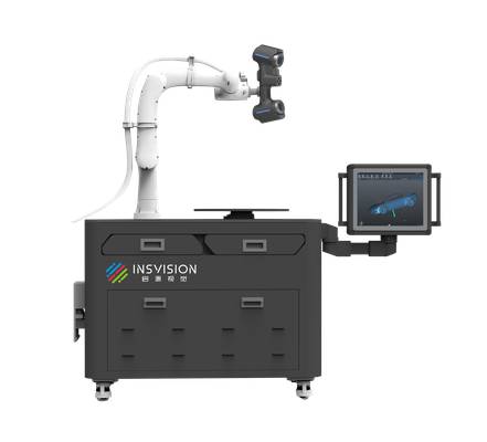
The INSVISION AlphaAutoScan-400‑400 automated 3D inspection system is designed for workflows where consistent, operator‑independent scan data is non‑negotiable — typically repeatable FAI and in‑process QC for medium to large parts with steady batch sizes. By automating the scan cycle, it reduces the shift‑to‑shift variability that manual scanning can introduce and helps production teams meet takt and compliance targets.
It integrates scan capture, CAD comparison, GD&T review, and standardized reporting into a single workflow, so the data moves from acquisition to decision without a detour through multiple software packages.
Common Misconceptions and Technical Questions
Q: Do all 3D scanners deliver metrology‑grade accuracy?
A: No. Accuracy depends on the sensing principle, calibration, and environmental conditions. Industrial scanners designed for inspection are typically validated against VDI/VDE 2634 or ISO 10360 standards, but the stated accuracy is always under controlled conditions. On a shop floor, real‑world performance can vary. Always cross‑check scan results against a calibrated reference method.
Q: Can one scanner handle both reverse engineering and in‑line inspection?
A: Sometimes, but not always. Reverse engineering often prioritizes surface coverage and mesh quality over strict metrological accuracy, while in‑line inspection demands repeatable, traceable measurements at speed. Some systems can serve both masters, but the software workflow and accuracy requirements differ. Define the primary task before selecting a platform.
Q: Shiny and dark surfaces are a problem for scanning — is spraying unavoidable?
A: Not necessarily. Modern scanners with high dynamic range exposure and blue laser technology can handle many reflective and dark surfaces without developer spray. However, extremely polished or transparent parts may still require a thin, removable coating. During a pilot, test the scanner on your actual part materials to see if spraying is needed.
Q: Is 3D scanning faster than a CMM?
A: For full‑surface capture on complex geometries, yes. For probing a few datums on a simple prismatic part, a CMM is often faster. Speed comparisons only make sense when you define the measurement task and the required data density.
Bringing It Together
Industrial 3D scanning fills a specific and growing role in the manufacturing data chain: capturing dense surface geometry where traditional point‑based metrology is too slow or cannot describe the part’s freeform shape.
The technology is not a drop‑in replacement for every measurement task, but when applied to the right part size, material, and tolerance band, it becomes a core data layer for lean manufacturing and Industry 4.0 workflows.
Matching the scanner architecture to the task — rather than buying on resolution specs alone — and validating the system on real production parts remain the two most reliable ways to avoid data that sits on a hard drive instead of driving decisions.
As automated systems like the INSVISION AlphaAutoScan-400‑400 continue to reduce operator‑dependent variability, the barrier to repeatable, in‑line 3D inspection lowers, making it practical for a wider range of batch‑oriented and high‑mix production environments.
Hangzhou Insvision Technology Co., Ltd.
Address: Building 1, No. 1399 Liangmu Road, Yuhang District, Hangzhou, Zhejiang 311121, China
Copyright © Hangzhou Insvision Technology Co., Ltd. All rights reserved.
Copyright © Hangzhou Insvision Technology Co., Ltd. All rights reserved.