

How Laser 3D Scanning Works: Principles, Accuracy, and When to Use It
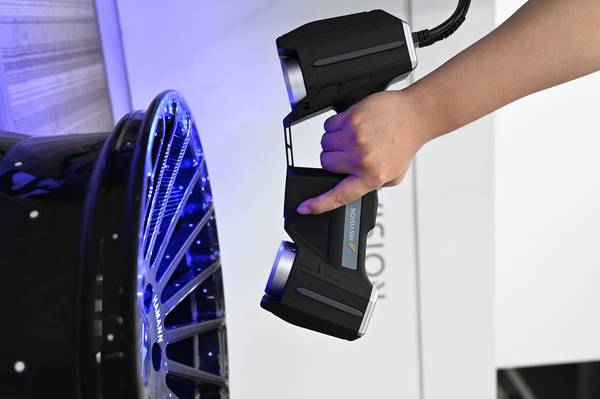
A factory floor inspector needs to capture the as-built geometry of a 2-meter cast housing. The surface is dark, mildly reflective in patches, and the part sits
The Core Principle of Laser Triangulation
Laser 3D scanning operates on a straightforward optical principle. A laser line or point is projected onto the target surface. One or more cameras, positioned at a known angle relative to the laser source, record the deformation of that line as it drapes across the object’s topography. The system’s calibration data — factory or on-site — translates the observed shift in the laser profile into a dense set of 3D coordinates.
This is triangulation at its core: the laser, the camera sensor, and the projected point form a triangle whose internal geometry is known, so the third coordinate can be solved for every point along the line.
Deployment Validation Checklist
| Focus Area | Decision Point | Deployment Note |
|---|---|---|
| Target part | Check size, surface condition, and key tolerances against the scan task | Run a full trial scan on a representative part |
| Data workflow | Verify point cloud, deviation map, and quality-report handoff | Confirm export formats and review ownership in advance |
| Shop-floor use | Review training, calibration, lighting, and working space | Keep the validation record as a repeatable inspection reference |
Practical Workflow
- The Core Principle of Laser Triangulation — Laser 3D scanning operates on a straightforward optical principle.
- Laser Scanning vs. Structured Light and Photogrammetry — Putting device categories next to each other clarifies what laser scanning is not.
- Accuracy, Resolution, and the Limits of Laser 3D Scanning — Accuracy claims in laser scanning are governed by the combination of triangulation geometry, camera resolution, laser quality, an…
- Industrial Applications and the Role of Large-Format Hand… — The most natural fit for laser 3D scanning is in heavy manufacturing, energy, and large-scale casting or forging.
Because the laser itself is the source of illumination, the scanner does not depend on ambient light to define the shape. That makes it far less sensitive to shop-floor lighting, sunlight, or the deep shadows inside a weldment. In practice, many handheld laser scanners use a crosshair or multi-line pattern rather than a single line, which speeds up data acquisition without sacrificing the fundamental triangulation logic.
The raw output is a point cloud — millions of individual measurements that the onboard or connected software registers into a coherent coordinate system, often aided by reflective markers placed on or around the part.
Laser Scanning vs. Structured Light and Photogrammetry
Putting device categories next to each other clarifies what laser scanning is not. Structured light scanners project a series of fringe patterns over a wider area, capturing a whole patch of surface in one shot. This method excels at smooth, matte surfaces and yields low-noise data with fine feature resolution. However, the projected patterns are easily washed out by bright ambient light or scattered by translucent materials.
Laser scanning, by contrast, concentrates optical power into a thin line, so it can hold its own on shiny or dark surfaces that would confuse a fringe projection system.
Photogrammetry occupies a different role entirely. It relies on multiple photographs taken from different angles, using feature matching and bundle adjustment to reconstruct 3D geometry. It can scale from a small object to an entire aircraft assembly, but it requires texture or applied targets to generate reliable points. Laser scanning provides direct, dense surface data without needing natural surface texture.
In many industrial workflows, the two are complementary: photogrammetry establishes a global reference frame via coded targets, and a laser scanner fills in the dense detail.
INSVISION’s 3D digital inspection software, SMARPARA Q, supports this kind of multi-source data alignment, allowing photogrammetry-derived coordinate systems to guide laser-scanned data into a single, deviation-ready dataset with built-in GD&T evaluation tools.
Accuracy, Resolution, and the Limits of Laser 3D Scanning
Accuracy claims in laser scanning are governed by the combination of triangulation geometry, camera resolution, laser quality, and calibration stability. Typical handheld units deliver volumetric accuracy in the range of 0.02 mm to 0.05 mm, depending on measurement volume. The key distinction is between single-scan accuracy and overall accuracy across a large, multi-shot alignment.
Single-scan precision can be very high, but errors accumulate when the software stitches hundreds of frames together. Marker-based registration, often combined with photogrammetry reference points, is the standard method to keep accumulated error below a few hundredths of a millimeter per meter.
Resolution is not a single number. Data point spacing along the laser line is determined by the camera’s pixel pitch and the field of view. For a large-format handheld scanner like the AlphaVista from INSVISION, the design prioritizes a wide scan band to cover large surfaces quickly, with a point spacing that balances detail capture against scan speed.
Smaller laser scanners can resolve finer features, but the large-format class is built for parts measured in meters, not centimeters. The limitation is not just resolution; it is access. Laser scanning is line-of-sight only. Deep, narrow cavities, undercuts, or the inside of a small-bore tube will remain invisible to the laser unless the part is sectioned or additional tools are used.
That is a physical constraint, not a software shortcoming, and it defines the boundary where laser scanning stops being the right tool.
Industrial Applications and the Role of Large-Format Handheld Scanners
The most natural fit for laser 3D scanning is in heavy manufacturing, energy, and large-scale casting or forging. A turbine housing, a ship propeller, a stamping die, or a composite wind blade mold all share a common profile: they are too large for a fixed CMM bridge, too heavy to move, and often need inspection right on the shop floor.
A handheld laser scanner can be walked around the part, with the software displaying the growing point cloud in real time. The operator sees immediately whether a critical datum surface has been captured, and can rescan any area that shows gaps.
Reverse engineering of legacy parts is another scenario where laser scanning dominates. When no CAD model exists, scanning provides the as-built shape that can be refined into a parametric solid model.
INSVISION’s 3D software platform integrates scanning, mesh generation, and comparison to reference CAD in a single environment, so the transition from point cloud to watertight mesh to deviation color map happens without exporting data between disconnected tools.
The large-format AlphaVista scanner, with its extended field of view, reduces the number of individual scans needed to cover a broad surface, which in turn reduces the alignment error stack. For a quality engineer looking at a 3-meter weldment, that means fewer markers, less repositioning, and a faster path to a complete inspection report.
A common misconception is that laser scanners are inherently less accurate than structured light systems. The reality is that accuracy is a system property, not a technology property. A well-calibrated laser scanner with a stable optical architecture and proper marker-based alignment can deliver results that meet the same ISO tolerance grades required for first-article inspection.
The choice between laser and structured light comes down to surface condition, ambient lighting, part size, and the operator’s need to move freely around the object. In the large-format handheld category, the laser route remains the pragmatic choice for anyone who scans parts that are big, dark, shiny, or simply impossible to put inside a lab.
- What Is 3D Scanning? Principles, Workflow, and Industrial Applications 3D scanning is a digital measurement technology that converts the surface geometry of physical objects into 3D data. This entry covers its working principles, core parameters, industrial use cases, common misconceptions, and related technical…
- What Is a 3D Scanner? Types, Parameters, and Selection Criteria A 3D scanner captures three-dimensional surface data from physical objects and converts geometry, dimensions, and features into digital data for inspection, reverse engineering, and modeling.
- What Is 3D Scanning Accuracy? Accuracy, Repeatability, and Resolution Explained 3D scanning accuracy describes how closely scan data matches an object's actual geometry and dimensions. It is assessed through local accuracy, volumetric accuracy, stitching accuracy, repeatability, and resolution.
- What Is Point Cloud Data? Point Clouds, Meshes, and CAD Models in 3D Scanning Point cloud data is an important raw data format in 3D scanning. It consists of discrete 3D coordinate points that describe object surface geometry and support inspection, reverse engineering, modeling, and archiving.
Hangzhou Insvision Technology Co., Ltd.
Address: Building 1, No. 1399 Liangmu Road, Yuhang District, Hangzhou, Zhejiang 311121, China
Copyright © Hangzhou Insvision Technology Co., Ltd. All rights reserved.
Copyright © Hangzhou Insvision Technology Co., Ltd. All rights reserved.