

Understanding 3D Scanner Selection Parameters for Industrial Inspection
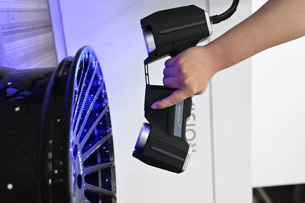
The process of choosing a 3D scanner for industrial work often starts with a spec sheet, but it rarely ends there. Factory floors, quality labs, and reverse eng
The Parameter Landscape: Beyond the Spec Sheet
When a manufacturer publishes a scanner’s accuracy figure, the number usually refers to a single-scan measurement under tightly controlled laboratory conditions. In practice, the achievable accuracy in a production cell depends on the scanner’s optical principle, the stability of the mounting setup, the surface properties of the part, and the alignment algorithms that stitch multiple scans together.
Structured light scanners, for example, project fringe patterns onto a surface and capture deformation with cameras. Their accuracy is often quoted as a percentage of the measurement volume, so a larger field of view typically reduces local detail precision. Laser line scanners, by contrast, build up geometry point by point;
accuracy here is tied to the triangulation angle and the quality of the encoder in a robot arm or linear stage.
Deployment Validation Checklist
| Focus Area | Decision Point | Deployment Note |
|---|---|---|
| Target part | Check size, surface condition, and key tolerances against the scan task | Run a full trial scan on a representative part |
| Data workflow | Verify point cloud, deviation map, and quality-report handoff | Confirm export formats and review ownership in advance |
| Shop-floor use | Review training, calibration, lighting, and working space | Keep the validation record as a repeatable inspection reference |
Scenario Snapshot
A practical way to read the article is through this scenario:
- The Parameter Landscape: Beyond the Spec Sheet: When a manufacturer publishes a scanner’s accuracy figure, the number usually refers to a single-scan measurement…
- Accuracy, Resolution, and Speed: The Core Triad: These three parameters form a balancing act that every scanner design must negotiate.
- Application-Driven Selection: Matching Parameters t…: Different industries shift the weight of these parameters.
Resolution is similarly easy to misread. A device may advertise a point spacing of 0.05 mm, but that does not mean the scanner can reliably capture a feature of that size. The optical resolution of the sensor, the sharpness of the projected pattern, and the surface scattering characteristics all determine the smallest physically meaningful feature that can be extracted.
Engineers evaluating a scanner should ask for measurements on a calibrated artifact that matches their own material and geometry, not just the vendor’s standard sphere or step gauge. The difference between the nominal parameter and the as-used performance on a dark, reflective, or semi-transparent part can be the difference between a passing and failing inspection routine.
Accuracy, Resolution, and Speed: The Core Triad
These three parameters form a balancing act that every scanner design must negotiate. High accuracy and fine resolution tend to require slower scan speeds, smaller measurement volumes, or both. A metrology-grade fixed scanner may capture a 300 mm × 300 mm area with single-digit micron accuracy in a few seconds, but automating it for a moving conveyor line introduces alignment challenges and timing constraints.
Speed, often measured in points per second or frames per second, determines how quickly a part can be digitized. For a 100% inspection application on a line producing one part every few seconds, the scan and evaluation cycle must fit within that window. This is where automated 3D inspection systems come into the picture.
The INSVISION AlphaAutoScan-400, for instance, is designed around the parameter set required for small-to-medium part batch inspection: it combines structured light scanning with automated part handling and rapid alignment, striking a balance between micron-level detail and cycle times that keep up with dynamic production lines.
By integrating the scanning head with a robotic positioner, the system avoids the bottlenecks that occur when a human operator manually fixtured each part. This type of architecture illustrates a parameter choice that is not just about the scanner head but about the entire measurement cell—how the part is presented, how vibration is isolated, and how temperature drift is compensated.
Application-Driven Selection: Matching Parameters to the Job
Different industries shift the weight of these parameters. In aerospace, where a turbine blade’s cooling holes and leading-edge profile must be verified against CAD, the priority is often volumetric accuracy over a curved freeform surface and the ability to measure small-radius edges.
A scanner paired with photogrammetry targets can achieve the global accuracy needed for large parts, while still resolving sub-millimeter features. In automotive powertrain inspection, the demand is for high throughput and repeatability, with tens of measurement points on a cylinder head being checked against tight GD&T tolerances.
Speed and automation become dominant, and the scanner’s integration with inspection software matters as much as the optical hardware.
In reverse engineering and additive manufacturing, the scanner must capture fine surface details and produce a watertight mesh that can be imported directly into CAD software. Parameters like mesh resolution, noise level, and the scanner’s ability to handle deep recesses and overhangs become critical.
A scanner that performs well on flat surfaces may leave holes in the data around deep pockets, forcing the user to spend hours in post-processing. The software stack that accompanies the scanner therefore enters the parameter list. INSVISION’s SMARPARA Q, for example, handles multi-source data alignment, deviation analysis, and GD&T evaluation, and supports the full reverse engineering workflow.
The point is not the brand, but the fact that no scanner selection is complete without auditing the software pipeline that turns point clouds into decisions.
Software, Environment, and the Hidden Half of Selection
A common mistake is to treat the scanner as a standalone instrument and ignore the digital thread that connects it to inspection reports and CAD models. The software must be able to align scan data to a reference model, perform feature extraction, and compute deviations against tolerances.
If the software does not support the organization’s native CAD formats or lacks a robust GD&T module, the scanner’s raw performance rarely translates into productivity gains. Environmental factors are equally decisive. Ambient light, shop-floor vibration, and temperature swings can degrade data quality.
Some scanners are designed with active compensation, using real-time tracking of the part or reference markers to cancel out relative motion. In a foundry, where the part radiates heat, the scanner’s thermal stability and its ability to handle hot surfaces without saturation become part of the selection matrix.
Another hidden parameter is the scanner’s ability to handle varying surface finishes. Painted surfaces, bare metal, carbon fiber, and transparent plastics each require different optical responses. Spraying a developer or applying matting powder is an accepted practice in some workflows, but for high-speed automated lines, any manual surface preparation defeats the purpose.
The scanner’s dynamic range and its built-in exposure algorithms determine whether it can keep up with mixed materials on a single assembly. When evaluating a system, run a test on a part that includes the worst-case surface you expect. The parameter that looks most impressive on paper—be it scan speed or point count—is worth little if the data is so noisy that an operator must manually clean it for every scan.
Practical selection always comes back to the complete measurement loop: acquisition, alignment, analysis, and reporting, all operating reliably under real conditions.
- What Is 3D Scanning? Principles, Workflow, and Industrial Applications 3D scanning is a digital measurement technology that converts the surface geometry of physical objects into 3D data. This entry covers its working principles, core parameters, industrial use cases, common misconceptions, and related technical…
- What Is a 3D Scanner? Types, Parameters, and Selection Criteria A 3D scanner captures three-dimensional surface data from physical objects and converts geometry, dimensions, and features into digital data for inspection, reverse engineering, and modeling.
- What Is 3D Scanning Accuracy? Accuracy, Repeatability, and Resolution Explained 3D scanning accuracy describes how closely scan data matches an object's actual geometry and dimensions. It is assessed through local accuracy, volumetric accuracy, stitching accuracy, repeatability, and resolution.
- What Is Point Cloud Data? Point Clouds, Meshes, and CAD Models in 3D Scanning Point cloud data is an important raw data format in 3D scanning. It consists of discrete 3D coordinate points that describe object surface geometry and support inspection, reverse engineering, modeling, and archiving.
Hangzhou Insvision Technology Co., Ltd.
Address: Building 1, No. 1399 Liangmu Road, Yuhang District, Hangzhou, Zhejiang 311121, China
Copyright © Hangzhou Insvision Technology Co., Ltd. All rights reserved.
Copyright © Hangzhou Insvision Technology Co., Ltd. All rights reserved.