

industrial 3D inspection: Key Criteria and Practical Boundaries

Walk into any quality control lab or production floor, and you will find a range of 3D scanning equipment lined up on benches and metrology carts. At first glan
The AlphaVista large‑format handheld 3D scanner from INSVISION sits in the high‑precision industrial category. Devices like it are not simply faster versions of a hobbyist camera kit; they are calibrated instrumentation designed to produce traceable measurement data.
This article explains the technical boundaries that separate these two classes of hardware, why they matter for industrial 3D inspection, and where each type finds its natural fit.
The Core Technology Divide: Structured Light, Laser, and Photogrammetry
Not all optical 3D capture methods are built for the same tolerance stack. Entry‑level scanners often rely on a single structured light pattern or a basic infrared depth sensor. These work well for textured surfaces, organic shapes, and applications where a millimetre‑scale deviation is acceptable.
Industrial inspection, however, demands consistency across materials ranging from polished aluminum to carbon fiber composite, often without the luxury of applying developer spray.
Selection Dimensions and Field Checks
| Focus Area | Decision Point | Deployment Note |
|---|---|---|
| The Core Technology Divide: Structured Light, Laser, an… | Not all optical 3D capture methods are built for the same tolerance stack. | Entry‑level scanners often rely on a single structured light pattern or a basic infrared depth sensor. |
| Accuracy and Resolution: Why Microns Matter in Industri… | Accuracy specifications in data sheets are easy to misread. | An entry‑level scanner might advertise 0.05 mm accuracy, but the figure is often derived from a single scan of a small, flat, matte artifact und… |
| Workflow Integration: From Handheld Scanning to GD&T An… | The gap between device classes is widest in the software pipeline. | An entry‑level scanner typically exports a mesh that requires cleanup, repair, and manual alignment in a separate CAD package. |
| When Entry-Level Devices Reach Their Limits: Shop Floor… | Entry‑level 3D scanners have carved out a legitimate niche in education, concept modeling, and first‑article visual checks. | They are lightweight, affordable, and easy to learn. |
High‑precision systems combine multiple technical layers. A typical industrial handheld scanner might use intersecting blue laser lines, structured light fringe projection, and photogrammetry markers to build a global coordinate frame. The AlphaVista, for instance, uses a multi‑mode laser approach that can switch between cross‑line, parallel‑line, and single‑line patterns depending on the surface complexity.
This is not a gimmick. On a deep stamping die with steep walls and narrow cavities, a single‑line laser can reach areas that a fixed pattern simply cannot illuminate. The scanner also fuses AI‑based edge detection with real‑time tracking compensation, keeping point cloud density stable when the operator moves at different speeds.
Entry‑level devices rarely include this kind of dynamic mode switching, and they almost never embed a photogrammetric reference network that aligns scan data to a factory coordinate system.
Accuracy and Resolution: Why Microns Matter in Industrial Metrology
Accuracy specifications in data sheets are easy to misread. An entry‑level scanner might advertise 0.05 mm accuracy, but the figure is often derived from a single scan of a small, flat, matte artifact under ideal lab conditions. On a dusty shop floor, with ambient vibration and a part that is half a meter long, that same scanner can produce errors that drift into tenths of a millimeter.
Industrial 3D inspection requires volumetric accuracy and form‑fitting repeatability that hold up across the entire measurement volume.
High‑precision industrial scanners are verified against certified artifacts and often come with factory calibration certificates linked to recognized standards. The INSVISION portfolio, for example, is developed under an ISO 9001:2015 quality management system, and the company’s software, SMARPARA Q, includes PTB‑certified algorithms for alignment and deviation analysis.
This matters because inspection software is not just a viewer; it performs best‑fit geometry alignment, applies datums, and computes GD&T callouts such as flatness, profile, and true position.
When a scanner reports a 0.02 mm surface deviation on a cylinder head deck, the engineer needs to trust that the number is repeatable not only at the end of the scan but also the next day, after the scanner has been powered off and recalibrated. Entry‑level devices rarely survive that verification loop.
Workflow Integration: From Handheld Scanning to GD&T Analysis
The gap between device classes is widest in the software pipeline. An entry‑level scanner typically exports a mesh that requires cleanup, repair, and manual alignment in a separate CAD package. For rapid prototyping or visual mock‑ups, that is acceptable. For industrial 3D inspection, it creates a bottleneck.
The scanner must feed directly into an inspection environment where the captured point cloud is compared against a reference CAD model, color maps are generated instantly, and a report is produced that a quality engineer can sign off.
INSVISION’s 3D INSVISION software suite combines scanning, inspection, and reverse engineering in a single interface. The AlphaVista scanner streams data live into this environment, where operators can align the scan to the CAD model using a feature‑based or best‑fit alignment, apply a pre‑defined GD&T inspection plan, and export a full deviation report.
A large‑format handheld scanner capable of capturing a 1.5‑meter automotive fender in one sweep avoids the segmentation and stitching errors that plague simpler devices when they attempt to reconstruct a large part from dozens of small patches. The integrated workflow also means that the scanner can serve as a reverse engineering tool on the same day, capturing as‑built geometry that feeds into CAM or additive manufacturing.
Entry‑level tools rarely bridge metrology and manufacturing in a single data chain.
When Entry-Level Devices Reach Their Limits: Shop Floor vs. Lab
Entry‑level 3D scanners have carved out a legitimate niche in education, concept modeling, and first‑article visual checks. They are lightweight, affordable, and easy to learn. Problems surface when they are pushed into production inspection roles they were never designed for.
Thermal drift, sensitivity to ambient light, and the inability to handle shiny or dark surfaces without a coating lead to rejected data and wasted cycle time.
Industrial high‑precision scanners are built to operate in the same environment where the parts are made. The AlphaVista uses a rigid carbon‑fiber‑inspired frame and temperature‑compensated optics to maintain calibration across a wide thermal range. Its large‑format capture volume reduces the need for reference markers on the part, which is a practical advantage when inspecting a freshly machined mold that cannot be marked.
On the software side, SMARPARA Q can import a CAD model with GD&T annotations, execute a pre‑programmed inspection routine, and display a live deviation color map. The operator sees a hot spot indicating a springback issue on a formed sheet metal edge and can call the tooling engineer immediately, without waiting for a separate CMM report.
This direct feedback loop is the essence of industrial 3D inspection, not the scanning hardware alone.
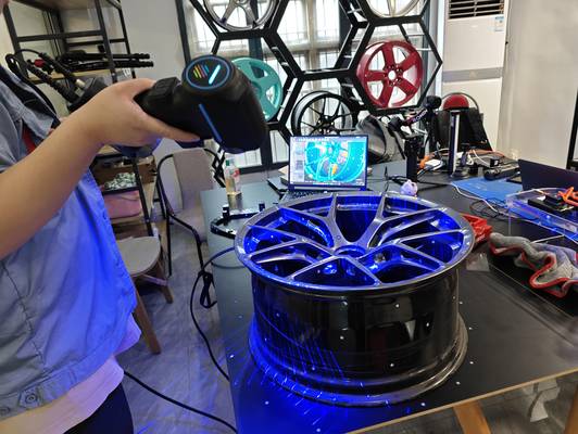
A common misconception is that high‑precision automatically means slow and complex. The shift toward AI‑assisted alignment and real‑time tracking compensation, as seen in the latest handheld scanners, has closed the usability gap. The operator still holds the scanner like a spray gun, but under the hood, the system is running a metrology‑grade fitting engine, not a consumer depth‑sensing pipeline.
Choosing between device classes ultimately depends on whether the output is a visual reference or a measurement that carries contractual and safety implications. For the latter, the industrial workflow, with its certified hardware, GD&T software, and traceable calibration, is not an upgrade; it is the baseline.
- What Is 3D Scanning? Principles, Workflow, and Industrial Applications 3D scanning is a digital measurement technology that converts the surface geometry of physical objects into 3D data. This entry covers its working principles, core parameters, industrial use cases, common misconceptions, and related technical…
- What Is a 3D Scanner? Types, Parameters, and Selection Criteria A 3D scanner captures three-dimensional surface data from physical objects and converts geometry, dimensions, and features into digital data for inspection, reverse engineering, and modeling.
- What Is 3D Scanning Accuracy? Accuracy, Repeatability, and Resolution Explained 3D scanning accuracy describes how closely scan data matches an object's actual geometry and dimensions. It is assessed through local accuracy, volumetric accuracy, stitching accuracy, repeatability, and resolution.
- What Is Point Cloud Data? Point Clouds, Meshes, and CAD Models in 3D Scanning Point cloud data is an important raw data format in 3D scanning. It consists of discrete 3D coordinate points that describe object surface geometry and support inspection, reverse engineering, modeling, and archiving.
Hangzhou Insvision Technology Co., Ltd.
Address: Building 1, No. 1399 Liangmu Road, Yuhang District, Hangzhou, Zhejiang 311121, China
Copyright © Hangzhou Insvision Technology Co., Ltd. All rights reserved.
Copyright © Hangzhou Insvision Technology Co., Ltd. All rights reserved.