

Point Cloud Data: Understanding the Foundation of 3D Scanning and Digital Modeling

A point cloud is exactly what the name suggests: a dense collection of points in three-dimensional space. Each point carries X, Y, and Z coordinates that record
What makes point cloud data genuinely useful is that the points also store additional attributes. Alongside position, many scanners capture intensity values, which reflect how much laser light returned from the surface. Some systems also encode color information, but in industrial applications, the critical extra channel is often the normal vector computed for each point.
This vector tells the software which direction the surface is facing at that spot, which is essential for aligning multiple scans and later generating a continuous mesh. Without these attributes, the cloud would be a shapeless swarm of digits. With them, it becomes a digital twin that can be inspected, compared to a CAD model, or machined.
Deployment Validation Checklist
| Focus Area | Decision Point | Deployment Note |
|---|---|---|
| Target part | Check size, surface condition, and key tolerances against the scan task | Run a full trial scan on a representative part |
| Data workflow | Verify point cloud, deviation map, and quality-report handoff | Confirm export formats and review ownership in advance |
| Shop-floor use | Review training, calibration, lighting, and working space | Keep the validation record as a repeatable inspection reference |
How Point Clouds Are Captured and What Determines Their Quality
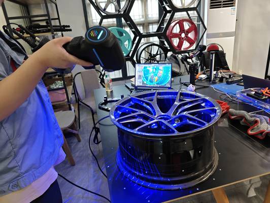
A professional 3D scanner builds a point cloud by projecting structured light or laser lines onto a surface and recording the deformed pattern with one or more cameras. The scanner’s software triangulates the positions of thousands or millions of surface points per second.
The density and accuracy of the resulting cloud depend on several factors: the resolution of the cameras, the wavelength and quality of the light source, the calibration stability, and the scanning strategy.
Practical Workflow
- How Point Clouds Are Captured and What Determines Their Q… — A professional 3D scanner builds a point cloud by projecting structured light or laser lines onto a surface and recording the def…
- From Raw Points to Usable Data: Cleaning, Alignment, and… — A freshly captured point cloud is rarely ready for engineering use.
- The Mesh Transition and the Misconception About Point Clo… — A point cloud is not a solid model.
- Industrial Applications and the Limits of Point Cloud Data — Point cloud data is the backbone of automated inspection lines, where speed and repeatability are non-negotiable.
Blue laser technology has become the standard for industrial scanning because shorter wavelengths produce less speckle noise on reflective and dark surfaces. A system like the AlphaAutoScan-400 from INSVISION uses 50 cross blue laser lines to capture fine details in a single pass.
That number of lines matters because it increases the probability that crevices, edges, and small feature shifts are sampled from multiple angles simultaneously. The result is a point cloud that faithfully records geometry down to a metrology-grade accuracy of 0.020 mm.
Achieving that level of precision requires not just high-resolution optics but also a stable mechanical frame and an automated scanning path that eliminates the jitter and alignment errors common in handheld workflows.
From Raw Points to Usable Data: Cleaning, Alignment, and Registration
A freshly captured point cloud is rarely ready for engineering use. It contains noise, duplicates, and sometimes points that belong to the fixture or the scanning table rather than the part itself. The first practical step is always segmentation and outlier removal. Software algorithms identify points that deviate from the local surface continuity and strip them out.
Where multiple scans from different orientations overlap, the software must align them into a unified coordinate system. This process is called registration, and it often relies on either marker targets placed on the part or on feature-based matching that recognizes distinctive surface geometry.
Once all scans are registered, the combined point cloud is resampled or decimated to reduce file size while preserving the surface detail that matters. This is a balancing act. Too aggressive a reduction and you lose the sharp edges of a machined pocket. Too little and the dataset becomes unwieldy for downstream CAD or inspection software.
The editing stage is where the point cloud shifts from a raw measurement dump to a structured, clean dataset that can be trusted for dimensional inspection or reverse engineering. INSVISION’s software platforms, including the V-Track and AlphaScan toolchains, handle this through a dedicated “Point cloud scanning and processing” module that walks the operator from raw scan data to a refined point set ready for meshing.
The Mesh Transition and the Misconception About Point Clouds
A point cloud is not a solid model. It is not even a polygon mesh. One of the most common misconceptions among engineers new to 3D scanning is that a point cloud can be imported directly into CAD software and used for parametric modeling. In practice, the point cloud must first be converted into a mesh—a network of triangles that connects neighboring points into a continuous surface.
This mesh can then be optimized, smoothed, and patched to fill any small holes where the scanner could not reach.
The mesh is where the point cloud finally becomes a tangible digital asset. For inspection workflows, the mesh (or the point cloud itself) is aligned to the nominal CAD model, and a color map deviation report shows exactly where the manufactured part is out of tolerance.
For reverse engineering, the mesh is the starting point for extracting cross-sections, fitting geometric primitives, and reconstructing a parametric CAD model that can be modified in a standard engineering workstation. Aerospace and automotive rebuilders, for instance, frequently use scanned point clouds of legacy parts—like turbine housings or airframe components—that have no existing drawings.
The AlphaVista system from INSVISION is often deployed in such scenarios for wide-area scanning, capturing large surfaces as dense point clouds that can be turned into accurate CAD references for reproduction or modification.
Industrial Applications and the Limits of Point Cloud Data
Point cloud data is the backbone of automated inspection lines, where speed and repeatability are non-negotiable. Automated systems like the AlphaAutoScan-400 are built for production environments that demand batch inspection of small to medium-sized parts, with millisecond-level response times and the ability to detect micron-scale surface defects. In such settings, the point cloud is not just a historical record;
it is a live measurement used to accept or reject parts in real time.
Yet point clouds are not the right tool for every problem. They fail on geometries that are smaller than the scanner’s spot size or where the scanner cannot achieve line of sight. Deep, narrow holes with diameters under a few millimeters, for example, will not produce a usable point cloud with standard optical triangulation.
Similarly, transparent or highly specular surfaces can return misleading data unless the operator applies a temporary coating. The key to getting good results is understanding that a point cloud is a sampling of reality, not a perfect copy.
Knowing the scanner’s resolution, accuracy, and the material envelope you are working with determines whether the point cloud you generate will be suitable for your inspection tolerance or reverse engineering goal. When those boundaries are respected, point cloud data becomes one of the most reliable ways to bridge the physical and digital worlds in modern manufacturing.
- What Is 3D Scanning? Principles, Workflow, and Industrial Applications 3D scanning is a digital measurement technology that converts the surface geometry of physical objects into 3D data. This entry covers its working principles, core parameters, industrial use cases, common misconceptions, and related technical…
- What Is a 3D Scanner? Types, Parameters, and Selection Criteria A 3D scanner captures three-dimensional surface data from physical objects and converts geometry, dimensions, and features into digital data for inspection, reverse engineering, and modeling.
- What Is 3D Scanning Accuracy? Accuracy, Repeatability, and Resolution Explained 3D scanning accuracy describes how closely scan data matches an object's actual geometry and dimensions. It is assessed through local accuracy, volumetric accuracy, stitching accuracy, repeatability, and resolution.
- What Is Point Cloud Data? Point Clouds, Meshes, and CAD Models in 3D Scanning Point cloud data is an important raw data format in 3D scanning. It consists of discrete 3D coordinate points that describe object surface geometry and support inspection, reverse engineering, modeling, and archiving.
Hangzhou Insvision Technology Co., Ltd.
Address: Building 1, No. 1399 Liangmu Road, Yuhang District, Hangzhou, Zhejiang 311121, China
Copyright © Hangzhou Insvision Technology Co., Ltd. All rights reserved.
Copyright © Hangzhou Insvision Technology Co., Ltd. All rights reserved.