

Inspecting Valve Bodies and Manifolds: Where Geometry Meets Fluid Path Complexity
A fluid control component is never just a block of metal with a hole. A three-way ball valve body, for example, packs intersecting bores, sealing seats, threade
## Why Fluid Control Components Break Conventional Inspection Routines
The first hurdle is surface condition. Ball valve bodies and hydraulic manifolds often arrive at the inspection station with a mix of as-cast textures, bright machined lands, and dark oxide or passivation layers. A laser scanner that relies on a single exposure setting will either saturate the shiny flange or lose the dull threaded port. The second is accessibility.
The valve’s internal flow path, including cross-drilled intersections and seat pockets, sits in shadow from any one line of sight. A fixed CMM head cannot sweep the internal contours, and a borescope-based optical system gives only a qualitative view, not metrology-grade point clouds. The third is the datum structure.
A typical fluid control part drawing calls out primary, secondary, and tertiary datums on flange faces, mounting holes, and sometimes the centerline of a port. Touching off these datums with a hard probe is time-consuming and repeatable only if the part is rigid and the fixture is perfect. Thin-walled valve bodies crush slightly under even moderate clamping force, so the datum simulation itself becomes a source of error.
Finally, the inspection report often needs to prove not just that a bore diameter is within tolerance, but that the entire port axis is concentric to the sealing seat within a few microns, and that the mating flange face is perpendicular to that axis.
That kind of geometric tolerance callout is GD&T territory, and it demands a 3D dataset that captures everything in one coordinate system, not a collection of discrete point-to-point measurements.
Capability and Deployment Mapping
| Focus Area | Decision Point | Deployment Note |
|---|---|---|
| ## Why Fluid Control Components Break Conventional Insp… | The first hurdle is surface condition. | Ball valve bodies and hydraulic manifolds often arrive at the inspection station with a mix of as-cast textures, bright machined lands, and dark… |
| ## From Blue Laser Scanning to a Complete 3D Dataset | A handheld scanner like the INSVISION AlphaScan comes into the picture not as a replacement for CMMs, but as a way to acquire the full surface geomet… | The AlphaScan uses blue laser technology, which handles shiny and dark surfaces with far less noise than red laser alternatives, and its metrolo… |
| ## Turning Point Clouds into Inspection Reports | The raw scan data becomes an inspection report inside SMARPARA Q, the PTB-certified 3D inspection software that integrates with the AlphaScan workflo… | The process begins by importing the CAD model and the scan mesh, then executing a best-fit alignment constrained by the specified datum features. |
| ## Adapting the Workflow to Different Fluid Control Com… | The scanning strategy shifts slightly depending on the part family. | A small pneumatic valve manifold with a dozen threaded ports benefits from a fixture that holds the part on a turntable, with the AlphaScan moun… |
## From Blue Laser Scanning to a Complete 3D Dataset
A handheld scanner like the INSVISION AlphaScan comes into the picture not as a replacement for CMMs, but as a way to acquire the full surface geometry that a tactile probe cannot physically reach.
The AlphaScan uses blue laser technology, which handles shiny and dark surfaces with far less noise than red laser alternatives, and its metrology-grade design means the point clouds are dense enough to resolve small radius transitions, thread crests, and sealing lips.
The operator scans the valve body by moving around it, turning the part once to capture the external flanges, mounting lugs, and datum surfaces, then reorienting the component to let the laser enter the ports. The scanner’s software, 3D INSVISION, aligns the multiple scans automatically using the part’s geometry, so there is no need for target stickers on every surface.
For deep internal cavities, the operator can take a few extra passes at a steeper angle, and the AI-driven algorithms fill in thin areas where the laser line grazes the surface at a shallow angle. The result is a single, watertight mesh that represents the valve body exactly as it sits in a free state, without fixture-induced distortion.
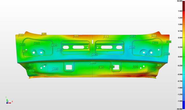
This is a crucial point: because the part is not clamped, the scan captures the as-built condition, and any warping or spring-back from machining is visible in the deviation map.
## Turning Point Clouds into Inspection Reports
The raw scan data becomes an inspection report inside SMARPARA Q, the PTB-certified 3D inspection software that integrates with the AlphaScan workflow. The process begins by importing the CAD model and the scan mesh, then executing a best-fit alignment constrained by the specified datum features.
The software’s GD&T tools allow the inspector to define concentricity, perpendicularity, position, and profile tolerances directly on the 3D data, and the color map shows instantly whether the valve body complies. For a typical three-way ball valve, the engineer might check the profile of the internal bore intersection, the flatness of the flange faces, and the angular relationship between the stem bore and the inlet port.
Each check is traceable and repeatable, and the report can be exported as a PDF or as a digital package that the customer can review. What often gets overlooked is the downstream value of having the complete scan data. When a batch of castings shows a trend toward undersize bores, the team can overlay the scan data from multiple parts and see the pattern immediately.
That feedback loop connects the inspection room to the foundry or the machining cell, and the same scan data can be archived for future re-inspection or for reverse engineering if the CAD model is ever lost.
## Adapting the Workflow to Different Fluid Control Components
The scanning strategy shifts slightly depending on the part family. A small pneumatic valve manifold with a dozen threaded ports benefits from a fixture that holds the part on a turntable, with the AlphaScan mounted on a tripod for repeatable passes. The scanner’s high frame rate keeps the scan time short enough that an operator can finish a part in under three minutes, which fits a batch inspection rhythm.
Larger hydraulic valve bodies, which may weigh several kilograms, are scanned handheld while resting on a simple V-block. The operator concentrates on the sealing surfaces and the port threads, and the software’s smart alignment automatically registers the data even when the part is moved between scans. The common thread is that the inspection strategy is driven by the part geometry, not by the tool’s limitations.
If a critical seat is hidden behind a threaded boss, the operator can tilt the scanner and aim the laser at the accessible edge, and the software will reconstruct the surface from the visible portion. The AI-assisted algorithms inside the INSVISION system handle the interpolation intelligently, flagging areas where the data density is lower so the operator can decide whether to take an additional pass.
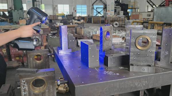
When a quality manager asks whether a valve body will seal against a mating flange under pressure, the answer is no longer derived from a handful of point measurements—it is visible in the deviation map of the entire sealing face. INSVISION’s AlphaScan and the SMARPARA Q software provide the hardware and software backbone to make that workflow practical on the shop floor, not just in a lab.
The result is a faster, more complete, and more defensible inspection process that starts with the part itself and ends with a report that tells the whole story.
Hangzhou Insvision Technology Co., Ltd.
Address: Building 1, No. 1399 Liangmu Road, Yuhang District, Hangzhou, Zhejiang 311121, China