

What Makes 3D scanning for large molds Difficult to Capture Accurately
## The Anatomy of a Large Mold as a Measurement Target A large mold is rarely a simple block of steel. It can be a forging die with contoured parting lines that
The Anatomy of a Large Mold as a Measurement Target
A large mold is rarely a simple block of steel. It can be a forging die with contoured parting lines that curve across two meters of tool steel, a composite layup mold with a gel-coated surface that glares under shop lights, or a sand-casting pattern where deep, narrow pockets trap air and light.
The material itself sets the first hurdle: polished tool steel acts like a mirror, while dark, oxidized surfaces on a well-used die soak up laser energy and return weak signals. Grains and textures on cast iron patterns scatter light in unpredictable directions, and the same mold may have machined reference faces, hand-finished cavities, and weld-repaired areas, each with a different optical response.
Deployment Validation Checklist
| Focus Area | Decision Point | Deployment Note |
|---|---|---|
| Target part | Check size, surface condition, and key tolerances against the scan task | Run a full trial scan on a representative part |
| Data workflow | Verify point cloud, deviation map, and quality-report handoff | Confirm export formats and review ownership in advance |
| Shop-floor use | Review training, calibration, lighting, and working space | Keep the validation record as a repeatable inspection reference |
Scenario Snapshot
A practical way to read the article is through this scenario:
- The Anatomy of a Large Mold as a Measurement Target: A large mold is rarely a simple block of steel.
- Where Traditional Inspection Falls Short on Large T…: Contact probing on a large mold is a game of patience.
- Building a 3D Scanning Workflow Around Wireless Tra…: A practical approach starts with freeing the scanner from a fixed coordinate system.
Size is another dimension of the problem. Molds that weigh several tons cannot be moved to a coordinate measuring machine every time a wear check is needed. Their sheer volume makes conventional contact probing slow, and the stylus cannot reach every undercut or deep rib. Then there is the geometry itself: steep walls, deep bosses, narrow slots, and blended radii that flow into flat roofs.
A few degrees of draft angle can hide a section of the cavity from a single line of sight, and the real defect a toolmaker cares about might be localized erosion at the bottom of a deep pocket, exactly where a probe or a fixed camera struggles to collect reliable points.
Add to this the fact that many molds are measured in a press or on the shop floor, where vibration, ambient light, and temperature swings are part of the environment, and the measurement task becomes a tightrope walk between speed, coverage, and trustworthy data.
Where Traditional Inspection Falls Short on Large Tooling
Contact probing on a large mold is a game of patience. A technician sets up a part alignment, touches off a few dozen or a few hundred points, and then tries to guess what happened between those points. The result is a sparse report that can miss localized wear, sink marks, or gradual wall thinning.
Moving a heavy mold to a climate-controlled CMM room disrupts production and introduces thermal soak differences that can render measurements irrelevant. Laser trackers combined with handheld probes improve reach but still leave the operator sampling discrete locations, and the surfaces between those points remain invisible.
A full-field 3D scan rewrites that logic. Instead of a handful of measured points, the mold surface is captured as a dense point cloud, often with sub-millimeter spacing, so the entire cavity, parting line, and even the sprue and runner system become a digital twin. This is especially valuable on large molds where wear patterns are not uniform.
A forging die might erode at the flash gutter and the cavity bottom simultaneously, while the side walls stay intact. Only a continuous surface comparison can reveal both regions in one pass, and that comparison is only useful if the scan data can be aligned to the original CAD model with a shared reference frame. For large molds, that alignment is far from trivial.
The scanner must know where it is relative to the part, and the part itself may have no natural flat datum; the only reliable references are often tooling balls, nested features, or a previous scan that already captured the entire mold.
Building a 3D Scanning Workflow Around Wireless Tracking and Blue Laser
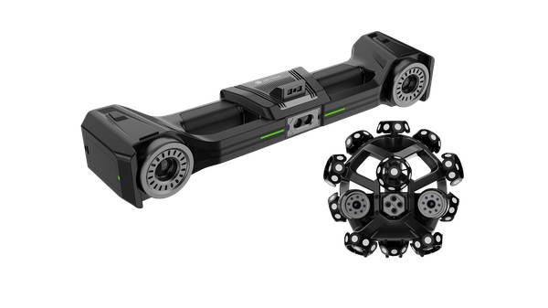
A practical approach starts with freeing the scanner from a fixed coordinate system. INSVISION’s X-Track wireless optical tracking system enables a handheld scanner to move freely around a large mold while the tracking unit continuously monitors the scanner’s position and orientation.
There is no need to attach markers all over the mold surface, and the setup avoids the vibrations and drift that can creep into arm-based or tripod-mounted systems.
The AlphaScan handheld blue laser scanner, paired with this tracking architecture, can walk around a mold that sits on the shop floor or remains mounted in the press, capturing surface geometry even on moderately reflective or dark surfaces without spraying the entire part.
The operator builds coverage by following the natural features of the mold. Deep cavities and undercuts are accessed by tilting the scanner and letting the tracking system stitch the data from multiple angles. The blue laser light helps maintain usable signal on shiny tool steel and on carbon-filled composite molds, reducing the need for developer sprays except in the most challenging mirror-finished areas.
As data accumulates, the 3D INSVISION software assembles a single, aligned point cloud. The software then overlays the CAD model and generates a color deviation map, making it immediately visible where the mold surface has worn, collapsed, or shifted.
For more rigorous dimensional analysis, SMARPARA Q handles GD&T callouts, profile tolerances, and multi-part alignment, producing reports that a tooling engineer can hand directly to a machining team for corrective action.
The entire loop, from scan start to deviation report, can happen in a fraction of the time a contact inspection would require for the same coverage. More importantly, it happens on the shop floor, with the mold at production temperature and in its working orientation.
That removes the uncertainty of thermal offsets and lets the team decide, based on a full-surface map, whether a mold can run another thousand cycles or needs to be pulled for rework.
From Deviation Reports to Repeatable Quality Loops
Once a deviation map shows where material is high or low, the next step is seldom a single correction. A deep cavity might be milled, re-scanned, and blended, then scanned again to confirm that the blending did not open a new low spot on an adjacent wall. The same AlphaScan and X-Track combination can be used for these iterative checks without a new setup, because the tracking system remembers the part’s reference frame.
That repeatability turns 3D scanning from a one-off inspection event into a monitoring tool that tracks wear progression over weeks and months.
For a forging die, periodic scans of the same cavity can be overlaid to measure erosion rates and to predict when a die will drop below the minimum wall thickness. For a large composite mold, thermal cycle scans can quantify how the tool moves during heating and cooling, helping the engineering team refine the cure cycle.
In pattern shops, a scan of a worn pattern can drive the machining of a replacement or a repair insert, with the scanned data flowing directly into CAM software. The digital thread does not end at the report; the same point cloud that flagged a deviation can become the basis for a machining offset, a simulation model, or a historical archive that proves the mold was within tolerance at the time of a specific production batch.
That is the quiet value of a well-built 3D scanning workflow on large molds: it converts a single inspection into a reusable asset that shapes decisions for the entire life of the tool.
Hangzhou Insvision Technology Co., Ltd.
Address: Building 1, No. 1399 Liangmu Road, Yuhang District, Hangzhou, Zhejiang 311121, China