

When the Part Won’t Fit on the CMM: 3D Inspection Strategy for Large Workpieces
A wind turbine gearbox housing fresh off the machining center sits on the shop floor. The quality team needs to verify flatness across a two-meter flange face,
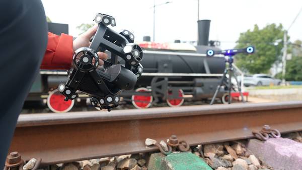
This scene repeats across heavy industry: large workpieces that push CMM capacity to the limit, combined with geometries that make traditional tactile inspection painfully slow. The challenge is not just size. It is the whole package: weight, surface finish, feature density, thermal stability, and the practical impossibility of repositioning a multi-ton casting to probe every hidden surface.
Inspection teams working with large castings, weldments, and machined structures increasingly pair optical tracking with handheld 3D scanning to break free from these constraints. The approach shifts the measurement logic — instead of bringing the part to the instrument, the instrument goes to the part, and the coordinate reference stays locked to the workpiece even when the scanner moves.
The Object Profile: What Makes Large Workpieces Difficult to Inspect
Large workpieces in heavy machinery, energy, shipbuilding, and aerospace tooling share a common set of inspection headaches. The first is thermal behavior. A casting that absorbs heat from a shop floor or direct sunlight can shift by hundredths of a millimeter over a two-meter span. Measuring it at 8 a.m. versus 2 p.m.
can produce different numbers, which means inspection must happen in a thermally stable window, or the data must be captured fast enough to minimize drift.
Capability and Deployment Mapping
| Focus Area | Decision Point | Deployment Note |
|---|---|---|
| The Object Profile: What Makes Large Workpieces Difficu… | Large workpieces in heavy machinery, energy, shipbuilding, and aerospace tooling share a common set of inspection headaches. | The first is thermal behavior. |
| Scanning Strategy: Building a Stable Reference Frame | For parts that exceed one meter in any dimension, the scanning strategy starts with the coordinate reference, not the scanner. | The INSVISION X-Track wireless optical tracking system addresses this by using a stereo camera unit that locks onto a set of fiducial markers at… |
| From Point Cloud to Decision: The Data Processing Chain | The raw output from a large-part scan is a dense point cloud, often tens of millions of points. | The processing chain turns this into actionable inspection data. |
| Choosing the Right Tool for the Scale | Not every large workpiece requires the same scanning approach. | A steel weldment with a tolerance of ±2 mm can be handled with a fast, lower-resolution scan. |
Surface condition is the second issue. Many large parts arrive with mill scale, sand-cast texture, or a light film of cutting fluid. Some surfaces are machined and reflective; others are raw and dark. A scanner that chokes on mixed reflectivity will leave data gaps right where the tolerance zone is tightest — typically around machined datum features surrounded by as-cast surfaces.
Then there is the geometry itself. Deep bores, internal ribs, undercuts, and flanges create shadow zones that a single line-of-sight device cannot reach. Feature density varies wildly: a planar face might have only a few reference points, while a bolting flange packs dozens of tapped holes into a tight pattern. The inspection workflow must handle both extremes without losing local detail or global accuracy.
Part handling adds another layer of difficulty. A large workpiece is not easily fixtured. It may sit on wooden blocks, a welding positioner, or a machine table. The reference frame must be established on the part itself, typically through tooling holes, machined datums, or temporary targets, rather than relying on a fixed external coordinate system.
Scanning Strategy: Building a Stable Reference Frame
For parts that exceed one meter in any dimension, the scanning strategy starts with the coordinate reference, not the scanner. The INSVISION X-Track wireless optical tracking system addresses this by using a stereo camera unit that locks onto a set of fiducial markers attached to the scanner or directly to the part.
Once the tracking system is positioned, the coordinate system is tied to the workpiece — move the scanner or the part, and the reference holds.
This optical tracking approach solves a practical problem on the shop floor. With a traditional arm-based system, the measurement volume is limited by the arm radius. With a tracker, the working volume is defined by the camera field of view and the marker layout. Operators can walk around a large casting, scan from multiple angles, and capture data from both sides of a flange without re-referencing.
The AlphaScan handheld scanner complements this setup by handling the surface-level challenges. Its blue laser projector works across mixed reflectivity, capturing machined steel and dark as-cast iron in the same scan sequence. For large planar areas, the scanner can operate in a rapid mode to capture the gross geometry quickly.
When the operator reaches a critical feature — a bearing bore, a dowel hole, a sealing surface — they can slow down and capture high-density data exactly where it matters.
A practical workflow for a large gearbox housing might look like this: place targets around the part, position the tracker, and scan the entire external surface in a continuous pass. Then insert the scanner into internal cavities to capture rib geometry and wall thickness.
For deep bores, a combined approach works — scan the bore entrance and exit, then measure the bore axis with a separate probing pass if the scanner cannot reach the full depth.
From Point Cloud to Decision: The Data Processing Chain
The raw output from a large-part scan is a dense point cloud, often tens of millions of points. The processing chain turns this into actionable inspection data.
The first step is alignment. If a CAD model exists, the software aligns the scanned data to the nominal geometry using feature-based, best-fit, or RPS alignment methods. The INSVISION 3D software platform handles this directly, supporting multiple alignment strategies depending on the datum scheme.
For parts without a CAD model — a common scenario in reverse engineering or legacy part replacement — the software can use a master part as the reference, comparing the scanned geometry to a known-good workpiece.
After alignment comes the comparison stage. The software generates a color map deviation plot, showing exactly where the part surface deviates from nominal. Red zones flag areas above the upper tolerance, blue zones indicate material below the lower tolerance, and green zones confirm surfaces within spec. This visual feedback is immediate and intuitive;
a shop floor supervisor can see at a glance whether a critical mating surface is within flatness tolerance.
Beyond the color map, the GD&T module handles specific callouts: flatness, cylindricity, position, profile, perpendicularity. The user selects the feature on the CAD model, and the software computes the deviation based on the scanned point cloud. For a bolting flange with twenty-four holes, the software can report position deviation for all holes in a single operation, saving hours compared to manual measurement.
The final deliverable is an inspection report. The software generates a formatted document with deviation plots, GD&T tables, and pass/fail flags, ready for quality documentation or customer submission. The entire chain — scan, align, compare, report — can be completed in under an hour for a part that would take a CMM half a shift.
Choosing the Right Tool for the Scale
Not every large workpiece requires the same scanning approach. A steel weldment with a tolerance of ±2 mm can be handled with a fast, lower-resolution scan. A machined bearing housing with a bore tolerance of ±0.03 mm demands metrology-grade data density and stringent tracker stability.
The decision starts with the tolerance band. For parts with critical features in the sub-0.1 mm range, the scanner needs proven volumetric accuracy, and the tracking system must maintain that accuracy across the full working volume. INSVISION positions the AlphaScan as a metrology-grade handheld scanner for exactly this use case, with the X-Track system extending that capability to large-scale parts.
The second factor is surface coverage. If the part has deep internal cavities, the scanner must be compact enough to access them. If the part has large unbroken surfaces, scan speed matters for practical throughput. A workflow that combines wide-area rapid scanning with localized high-density capture gives the operator control over both speed and detail.
The third factor is the software environment. The inspection team needs a platform that handles the full workflow without exporting data to external tools. The 3D INSVISION platform integrates scan control, alignment, GD&T analysis, and report generation, which reduces the friction of moving between different software packages.
For quality teams managing large workpieces, the shift from tactile-only inspection to a combined optical tracking and 3D scanning approach changes what is practical to measure. Features that were once skipped because they were too difficult to access become measurable. Inspection cycles that tied up CMM capacity for hours shrink to the time it takes to walk around the part with a scanner.
The technology is not a wholesale replacement for CMMs or manual gauging, but it solves a specific, persistent problem: how to get comprehensive dimensional data on parts that are simply too big, too heavy, or too awkward to inspect any other way.
Hangzhou Insvision Technology Co., Ltd.
Address: Building 1, No. 1399 Liangmu Road, Yuhang District, Hangzhou, Zhejiang 311121, China