

Deep-Cavity Data Capture in 3D Scanning: Definition, Principles, and Key Considerations
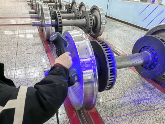
Deep-cavity data capture refers to the ability of a 3D scanning system to acquire accurate surface geometry from narrow, recessed, or internal features—such as
What Is Deep-Cavity Data Capture in 3D Scanning
In industrial metrology and reverse engineering, a deep cavity is generally a feature whose depth-to-opening ratio exceeds a threshold that challenges standard optical scanners. The cavity may be blind, stepped, or undercut. Capturing its full internal geometry without sectioning the part requires a specific combination of scanner design, projection technique, and software processing.
Term Notes
In industrial metrology and reverse engineering, a deep cavity is generally a feature whose depth-to-opening ratio exceeds a…
Working PrincipleThe underlying principle is to deliver structured light or laser lines into the cavity and collect the reflected signal from…
Key Parameters and Selection CriteriaThe following table summarizes the parameters that influence deep-cavity scan quality and what to evaluate in practice.
Suitable and Unsuitable Use CasesSuitable scenarios:
Deep-cavity data capture is not merely about reaching a recessed area; it is about obtaining metrologically usable data—dense point clouds, low noise on steep walls, and reliable feature edges—from regions where the optical path is long, the field of view is constrained, and multiple reflections can corrupt the signal.
Working Principle
The underlying principle is to deliver structured light or laser lines into the cavity and collect the reflected signal from a viewpoint that can see the illuminated area.
- Miniaturized optical heads allow the scanner to be positioned partway inside an opening.
- Oblique projection and off-axis viewing can sidestep the occlusion that a coaxial arrangement would suffer.
- Multi-line laser patterns or adaptive pattern density help maintain point-to-point resolution on inclined walls.
- Software-based cavity filling uses geometric continuity assumptions to fill small residual gaps, but the primary data must come from direct measurement.
The scanner projects a known pattern. Depending on the cavity depth, the pattern may be compressed or partially blocked. The imaging sensor captures the distorted pattern, and triangulation reconstructs the 3D coordinates. In deep cavities, dynamic exposure control and high dynamic range (HDR) imaging are often required to handle the steep drop in illumination from the cavity opening to the bottom.
Key Parameters and Selection Criteria
The following table summarizes the parameters that influence deep-cavity scan quality and what to evaluate in practice.
| Parameter | What It Affects | How to Evaluate |
|---|---|---|
| Standoff distance and minimum working distance | Determines whether the scanner can physically reach the cavity entrance | Measure the shortest distance from the scanner front to the first usable data point; compare with the cavity opening diameter and depth. |
| Field of view (FOV) at close range | Controls how much of the cavity wall is captured per frame | Request a FOV chart at the minimum working distance, not just the nominal FOV. |
| Laser line profile or pattern density | Influences point spacing on steep walls | Check the number of lines and the angular spread; a denser pattern helps maintain data on near-vertical surfaces. |
| Camera baseline and triangulation angle | Affects accuracy in narrow spaces | A longer baseline can improve accuracy but may increase shadowing; some scanners use a folded optical path to balance both. |
| Grazing angle performance | Determines how well data is captured on surfaces nearly parallel to the line of sight | Look for specifications on scanning angle tolerance, typically up to 85° or more from normal. |
| HDR and exposure speed | Prevents overexposure near the opening and underexposure deep inside | Ask about the scanner’s HDR cycle time; multi-exposure per frame is critical for deep cavities. |
| Software cavity-filling algorithms | Fills small unmeasurable zones (e.g., the very bottom of a blind hole) | Understand the maximum gap size that can be intelligently filled and whether the filled data is flagged for downstream inspection. |
Suitable and Unsuitable Use Cases
Suitable scenarios:
- Measuring injection mold cavities, die-casting die inserts, and deep pockets in machined components.
- Documenting internal features of valve bodies, hydraulic manifolds, and pump housings.
- Reverse engineering of impellers with deep, narrow blade passages.
- Inspecting cooling channels or conformal cooling features in tooling.
Less suitable or challenging scenarios:
- Blind holes with a depth-to-diameter ratio above approximately 5:1, where the scanner head cannot enter and the bottom remains unilluminated.
- Highly reflective or transparent internal surfaces without matting spray; deep cavities intensify stray reflections.
- Parts with undercuts where the scanner cannot achieve a clear line of sight at any practical angle.
- In-line inspection of moving parts where the required multi-exposure HDR slows the cycle time.
Common Misconceptions
- “If the scanner fits inside the cavity, it can scan it.” Physical access is necessary but not sufficient. The optical system must still have a clear triangulation path and adequate illumination for the entire depth.
- “Software can fill any missing data.” Cavity-filling algorithms work on small, well-bounded gaps. They cannot reconstruct a complex internal profile that was never optically sampled.
- “Higher resolution always improves deep-cavity results.” Excessively high resolution can produce noisy data on steep walls if the scanner’s exposure system cannot keep up. Practical resolution, combined with HDR, often matters more.
Related Concepts
| Concept | Distinction from Deep-Cavity Data Capture |
|---|---|
| General 3D scanning | Focuses on external, accessible surfaces; deep-cavity scanning requires specialized optical design and close-range performance. |
| Structured light scanning | Often uses a projector-camera arrangement that can be too bulky for cavities; some handheld structured light scanners overcome this with miniaturized optics. |
| Photogrammetry | Provides reference markers but cannot measure internal cavity geometry directly. |
| CT scanning (computed tomography) | Can capture full internal geometry including completely enclosed cavities, but is slower, more expensive, and limited by part size and material density. |
Relationship with INSVISION AlphaScan and Related Solutions
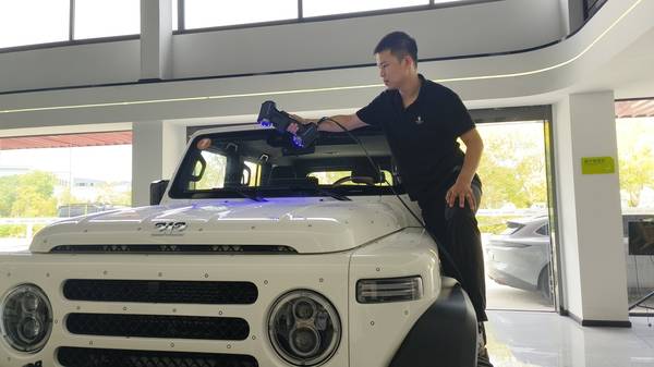
INSVISION’s AlphaScan handheld 3D scanner addresses deep-cavity data capture through a compact optical design and adaptive multi-line laser projection. The scanner’s short minimum working distance and high-density laser pattern allow operators to position the device near cavity openings and recover shape data from walls that are steeply angled relative to the scanner.
Dynamic HDR processing helps maintain usable data from the cavity rim down to the accessible depth. In industrial workflows—such as mold inspection, hydraulic component verification, and powertrain part digitization—AlphaScan is used to reduce the need for physical sectioning or silicone casting, while the resulting point clouds can be directly compared to CAD models in metrology software.
INSVISION’s approach emphasizes data quality from the actual measurement, rather than relying heavily on software interpolation, which is relevant when the internal geometry must meet tight tolerance requirements.
FAQ
What is the practical limit for deep-cavity depth-to-diameter ratio with a handheld scanner?
There is no universal number. It depends on the scanner’s minimum working distance, FOV, and the cavity’s wall taper. A skilled operator can often capture usable data from cavities with a ratio around 3:1 to 5:1, provided the opening diameter is larger than the scanner’s front-end width.
Does deep-cavity scanning require a different scanner than general-purpose scanning?
Not necessarily a completely different scanner, but a scanner that specifies close-range performance and deep-cavity capability. Many general-purpose handheld scanners can handle moderate cavities if their optical head is slim enough and their exposure system is fast.
Can deep-cavity scanning replace CT inspection?
It can replace CT in cases where the cavity is open and accessible. For fully enclosed internal voids or extremely narrow passages, CT remains the only non-destructive method.
How does surface finish affect deep-cavity scanning?
Machined cavity walls often have directional tool marks. These can create specular reflections that degrade data. Applying a thin, uniform layer of scanning spray is common practice, but it adds a thickness offset that must be accounted for in metrology.
Summary
Deep-cavity data capture in 3D scanning is a specialized capability defined by the interplay of optical reach, triangulation geometry, and dynamic exposure control. It is not a single scanner feature but a system-level performance characteristic that determines whether internal features can be measured reliably.
When evaluating equipment for such tasks, attention should focus on close-range FOV, grazing angle tolerance, HDR speed, and the physical size of the scanner head, rather than on nominal accuracy alone. The INSVISION AlphaScan series exemplifies a handheld design tuned for these constraints, offering a practical option for industrial applications where deep cavities are part of the daily inspection workload.
- What Is 3D Scanning? Principles, Workflow, and Industrial Applications 3D scanning is a digital measurement technology that converts the surface geometry of physical objects into 3D data. This entry covers its working principles, core parameters, industrial use cases, common misconceptions, and related technical…
- What Is a 3D Scanner? Types, Parameters, and Selection Criteria A 3D scanner captures three-dimensional surface data from physical objects and converts geometry, dimensions, and features into digital data for inspection, reverse engineering, and modeling.
- What Is 3D Scanning Accuracy? Accuracy, Repeatability, and Resolution Explained 3D scanning accuracy describes how closely scan data matches an object's actual geometry and dimensions. It is assessed through local accuracy, volumetric accuracy, stitching accuracy, repeatability, and resolution.
- What Is Point Cloud Data? Point Clouds, Meshes, and CAD Models in 3D Scanning Point cloud data is an important raw data format in 3D scanning. It consists of discrete 3D coordinate points that describe object surface geometry and support inspection, reverse engineering, modeling, and archiving.
Hangzhou Insvision Technology Co., Ltd.
Address: Building 1, No. 1399 Liangmu Road, Yuhang District, Hangzhou, Zhejiang 311121, China