

Coordinate Systems in 3D Scanning
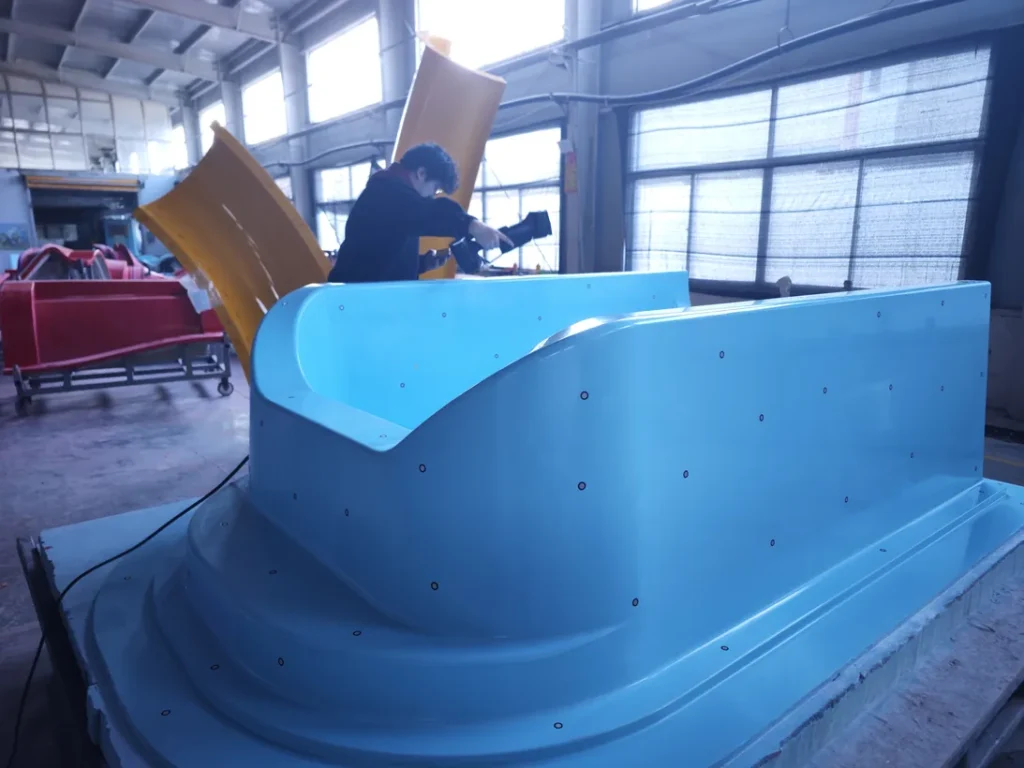
A coordinate system in 3D scanning is a standardized orthogonal reference frame used to assign unique numerical X, Y, and Z positions to every point captured during the scanning process.
Definition
A coordinate system in 3D scanning is a standardized orthogonal reference frame used to assign unique numerical X, Y, and Z positions to every point captured during the scanning process. It serves as the foundational structure for aligning multiple scan datasets, comparing scan data to design specifications, performing dimensional measurements, and integrating scan data with downstream industrial design, manufacturing, and inspection workflows. Most industrial 3D scanning coordinate systems follow the right-hand axis orientation convention, with a defined origin point and three mutually perpendicular axes.
How It Works
All 3D scanning systems first establish a local coordinate system during hardware calibration, mapping the relative positions of internal sensors (cameras, projectors, laser emitters) to a fixed origin tied to the scanner body. For each individual scan capture, points are plotted relative to this local frame, based on triangulation, structured light phase shift, or other core scanning principles. To combine multiple scans into a usable dataset, users register individual local frames into a single global coordinate system. Registration may use common surface features between overlapping scans, fixed fiducial markers placed on or near the scanned object, or real-time optical tracking that monitors the 6DoF (six degrees of freedom) position of the scanner relative to a fixed reference frame. For industrial measurement workflows, the global scan coordinate system is then aligned to an external reference frame, such as a part's datum reference frame defined in engineering drawings, a CAD model's native coordinate system, or a shop floor coordinate system used for machine tool or robot positioning. This alignment ensures that measurements derived from scan data match the specifications used for part design and manufacturing.
Key Parameters and Criteria
The performance of a 3D scanning coordinate system is evaluated against standardized, measurable parameters, all of which vary based on scanner hardware type, working volume, calibration status, and environmental conditions such as temperature, vibration, and ambient light. Key parameters include:
| Parameter | Meaning | Judgment Method |
|---|---|---|
| Coordinate System Accuracy | The maximum deviation between the measured 3D coordinates of calibrated reference artifacts and their certified nominal values | Compare scanned coordinates of traceable reference targets (e.g., gauge blocks, precision spheres) positioned across the full working volume of the system to their nominal values |
| Registration Error | The residual misalignment between individual scan frames when merged into a single global coordinate system | Calculate the root mean square (RMS) deviation of common fiducial markers or overlapping surface features across all aligned scan frames |
| Volumetric Consistency | The uniformity of coordinate measurement accuracy across the entire calibrated working volume of the scanning system | Measure reference targets placed at representative positions (center, edges, near and far bounds of the working volume) and compare the range of deviation values across all positions |
| External Alignment Tolerance | The maximum allowable deviation when aligning the scan coordinate system to an external reference frame (e.g., CAD model, shop floor datum, part engineering specification) | Compare the measured position of pre-defined datum features on the scanned part to their nominal positions in the target external reference frame |
Suitable and Unsuitable Scenarios
Suitable Scenarios
- Dimensional inspection and GD&T (Geometric Dimensioning and Tolerancing) analysis of industrial components, where scan data must be aligned to engineering datum reference frames to produce valid, auditable measurement results
- Large-volume scanning of assemblies such as automotive bodies, aerospace structures, or heavy machinery, where hundreds of individual scan frames must be merged into a single consistent reference frame
- Reverse engineering workflows, where scan data is exported to CAD software with a consistent coordinate system to support accurate remodeling and design iteration
- Automated scanning cells, where the scanning coordinate system is aligned to robot, machine tool, or conveyor coordinate systems to enable consistent part positioning and repeatable measurement cycles
Unsuitable Scenarios
- Use cases requiring measurement precision outside the calibrated working volume of the scanning system, as coordinate accuracy degrades rapidly beyond calibrated bounds
- Uncalibrated ad-hoc scanning with no defined reference frame, where data cannot be used for quantitative measurement or alignment to external design or manufacturing specifications
- Scenarios where coordinate systems are not re-calibrated after significant changes to hardware position, environmental conditions, or after physical impact to scanning or tracking hardware, leading to systematic measurement bias
- Cross-software data transfer without explicit coordinate system convention alignment, where mismatched axis orientation (left-hand vs right-hand rule) or unit scaling produces misaligned data
Common Misconceptions
- Misconception: Raw 3D scan data inherently uses a universal real-world coordinate system.
Fact: All raw scan data is initially mapped to a local coordinate system tied to the scanner's position at the time of capture. Explicit registration and alignment steps are required to map scan data to real-world, part-specific, or design-based reference frames.
- Misconception: A near-zero registration RMS error confirms a fully accurate global coordinate system.
Fact: Registration RMS only reflects the alignment consistency between overlapping scan frames. Systematic errors from hardware miscalibration, thermal distortion, or measurement outside the calibrated working volume can persist even with perfect registration scores.
- Misconception: A coordinate system remains valid permanently after initial factory calibration.
Fact: Coordinate system accuracy degrades over time due to hardware component drift, physical wear or damage to scanners and tracking hardware, and fluctuations in environmental conditions. Periodic re-calibration is required for all industrial 3D scanning systems.
- Misconception: The right-hand axis rule is universally used for all 3D scanning coordinate systems.
Fact: While most modern industrial 3D scanning systems follow the right-hand rule for axis orientation, some legacy inspection systems and specialized CAD platforms use left-hand rule frames. Explicit conversion is required during data transfer between systems to avoid mirroring or alignment errors.
Related Concepts
- 3D Scan Registration: The process of aligning multiple individual scan frames into a single unified global coordinate system
- Fiducial Marker: A high-contrast, dimensionally stable reference target used to align scan frames and establish consistent coordinate references
- Optical Tracking: A system that monitors the 6DoF position of scanners or objects in real time to extend and stabilize global coordinate systems for large-volume scanning
- Datum Reference Frame: The coordinate system defined by part features (e.g., holes, edges, mating surfaces) per engineering design specifications, used as the standard for inspection alignment
- Volumetric Accuracy: A system-level performance metric that describes the maximum coordinate measurement error across the entire calibrated working volume of a 3D scanning system
- Structured Light Calibration: The process of mapping the relative positions of cameras and projectors in structured light scanning systems to establish a consistent local coordinate system for capture
FAQ
What is the difference between a local and global coordinate system in 3D scanning?
A local coordinate system is a temporary, capture-specific reference frame tied to the position and orientation of the 3D scanner at the time of data collection, mapping all captured points relative to the scanner's internal sensors. A global coordinate system is a stable, project-wide reference frame that is aligned to part datums, engineering specifications, real-world positions, or CAD models, enabling consistent measurement, comparison, and analysis across all scan captures for a given part or project.
Do all 3D scanning use cases require alignment to an external coordinate system?
No. For qualitative use cases such as visual shape prototyping, artistic reference, or non-measurement visualization, raw scan data in a local coordinate system may be sufficient. All quantitative industrial use cases, including dimensional inspection, reverse engineering, assembly verification, and tooling validation, require alignment to a defined external coordinate system to produce repeatable, auditable results.
How frequently should a 3D scanning coordinate system be re-calibrated?
Re-calibration frequency depends on hardware type, usage intensity, and environmental conditions. Standard industrial practice requires re-calibration after any physical impact to the scanner, tracking hardware, or reference targets; after significant shifts in temperature, humidity, or vibration levels; after moving fixed scanning or tracking setups; and on a scheduled periodic basis (typically monthly to quarterly for high-usage systems) even in stable operating environments.
What are the most common causes of coordinate system misalignment?
Common causes include insufficient overlapping features or fiducial markers between individual scan frames, uncalibrated or miscalibrated scanner or tracking hardware, unintended movement of the scanned object or reference targets during data collection, environmental distortion from thermal expansion or vibration, and mismatched axis orientation or unit conventions between scanning software and downstream post-processing or analysis tools.
Summary
Coordinate systems are the foundational reference framework that enables quantitative, repeatable 3D scanning for industrial applications, providing a consistent structure to assign measurable 3D positions to all captured point data. Proper setup, calibration, and alignment of local capture frames and unified global coordinate systems are critical to ensuring scan accuracy, data compatibility, and validity for downstream workflows including dimensional inspection, reverse engineering, and manufacturing integration. Performance is evaluated via standardized metrics including coordinate accuracy, registration error, volumetric consistency, and external alignment tolerance, with results dependent on hardware type, calibration status, and operating conditions. Addressing common misconceptions around calibration permanence and universal coordinate conventions helps avoid avoidable measurement error and alignment issues in scanning projects.
- What Is 3D Scanning? Principles, Workflow, and Industrial Applications 3D scanning is a digital measurement technology that converts the surface geometry of physical objects into 3D data. This entry covers its working principles, core parameters, industrial use cases, common misconceptions, and related technical…
- What Is a 3D Scanner? Types, Parameters, and Selection Criteria A 3D scanner captures three-dimensional surface data from physical objects and converts geometry, dimensions, and features into digital data for inspection, reverse engineering, and modeling.
- What Is 3D Scanning Accuracy? Accuracy, Repeatability, and Resolution Explained 3D scanning accuracy describes how closely scan data matches an object's actual geometry and dimensions. It is assessed through local accuracy, volumetric accuracy, stitching accuracy, repeatability, and resolution.
- What Is Point Cloud Data? Point Clouds, Meshes, and CAD Models in 3D Scanning Point cloud data is an important raw data format in 3D scanning. It consists of discrete 3D coordinate points that describe object surface geometry and support inspection, reverse engineering, modeling, and archiving.
Hangzhou Insvision Technology Co., Ltd.
Address: Building 1, No. 1399 Liangmu Road, Yuhang District, Hangzhou, Zhejiang 311121, China
Copyright © Hangzhou Insvision Technology Co., Ltd. All rights reserved.
Copyright © Hangzhou Insvision Technology Co., Ltd. All rights reserved.