

Why Mold-Corner Inspection Fails Before It Even Starts
Injection mold cavities, blow mold pinch-offs, and deep draw tooling carry a predictable headache: the geometry that matters most for part quality sits where no
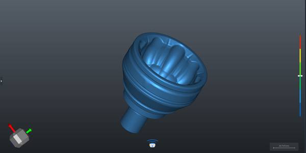
What makes mold corners uniquely difficult is not just access. The corner itself is a stress concentrator in service, and any deviation from the nominal radius shifts how the polymer fills, packs, and shrinks. A 0.2-millimeter erosion on a rib corner can change the entire cooling profile of the feature.
The challenge for dimensional inspection is to capture the actual 3D shape of the corner transition — not a point cloud with a dead zone, not a best-fit reconstruction that smooths over the warn zone, but the real as-is surface right where the two walls meet.
Deployment Validation Checklist
| Focus Area | Decision Point | Deployment Note |
|---|---|---|
| Target part | Check size, surface condition, and key tolerances against the scan task | Run a full trial scan on a representative part |
| Data workflow | Verify point cloud, deviation map, and quality-report handoff | Confirm export formats and review ownership in advance |
| Shop-floor use | Review training, calibration, lighting, and working space | Keep the validation record as a repeatable inspection reference |
Geometry That Defeats Line-of-Sight Instruments
A hard-to-reach mold corner rarely exists in isolation. It is usually surrounded by other geometry that blocks the sensor: a tall opposing wall, an ejector pin boss five millimeters away, a deep draw ratio that leaves the corner in shadow from every approach angle the operator tries first. For a fixed CMM, the probe assembly simply cannot reach the corner without a stylus extension so long that it introduces cosine error.
For a laser line scanner on a tripod, the projector-to-camera baseline loses the corner in the angle-of-incidence shadow.
Term Notes
A hard-to-reach mold corner rarely exists in isolation.
Surface State and the Data That Actually MattersMold corners are not pristine geometry.
Building a Scan Strategy That Closes the LoopA workflow that actually solves mold corner inspection starts with defining where the corners are and what level of coverage…
The traditional alternative to 3D scanning a mold corner is to section the tool or take a silicone cast and measure the cast…
The material of the mold steel adds another layer of difficulty. Polished P20, H13, or stainless mold inserts reflect light in a way that saturates many optical sensors. A corner that is both polished and deep acts as a light trap, bouncing the laser across multiple surfaces before any signal returns to the sensor. The result is a noisy fringe around the corner region, exactly where the analysis needs the cleanest data.
If the mold has been in production, the corner surface may also have a thin coating of mold release, gas residue, or micro-pitting, all of which further degrade the optical return.
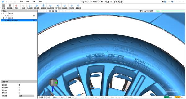
The AlphaScan handheld 3D scanner from INSVISION handles this class of geometry through a combination of short-standoff blue laser projection and a sensor head that can be angled into the cavity without losing tracking. The scanner does not require a rigid tripod setup or a fixed working distance.
An operator can tilt the device to align the laser plane with the corner bisector, capturing both walls and the radius transition in a single pass, then roll the scanner to fill in the opposite side. Because the instrument uses marker-free tracking on geometric features, it maintains registration even when the operator ducks the scanner into a deep pocket where the surrounding mold base is no longer visible.
Surface State and the Data That Actually Matters
Mold corners are not pristine geometry. On a new tool, the corner might still carry an EDM recast layer or a micro-milling scallop. On a tool with 50,000 cycles, the corner could show galling, micro-cracks, or a polished radius that has grown asymmetrically.
The inspection objective is not just to measure the radius, but to compare the entire corner surface to the nominal CAD model and identify the wear pattern: is it uniform erosion, localized pitting, or a shift in the parting line that has made one corner tighter than the opposing corner?
This is where point cloud density and edge definition separate usable data from unusable data. A scanner that smooths across the corner edge will hide the exact boundary where the wear analyst needs to draw a cross-section. The INSVISION AlphaScan captures up to 1.6 million points per second with a resolution that preserves the edge transition.
When the scan data is brought into inspection software, the operator can extract a true-to-life cross-section exactly at the corner root, overlay it on the CAD nominal, and generate a color map that shows deviation in the corner zone specifically. The wear pattern becomes visible as a gradient, not a binary pass/fail.
Mold surface color also affects measurement reliability. A dark nitrided insert corner, a copper-alloy core insert, or a polished chrome surface each present different optical challenges.
The AlphaScan adjusts exposure dynamically per frame, which means the operator can scan across a tool that has multiple surface finishes — a polished cavity next to a textured rib next to a dark PVD-coated slide — without stopping to recalibrate or spray developer. That matters in a production toolroom where the mold is not allowed to sit uncovered for long.
Building a Scan Strategy That Closes the Loop
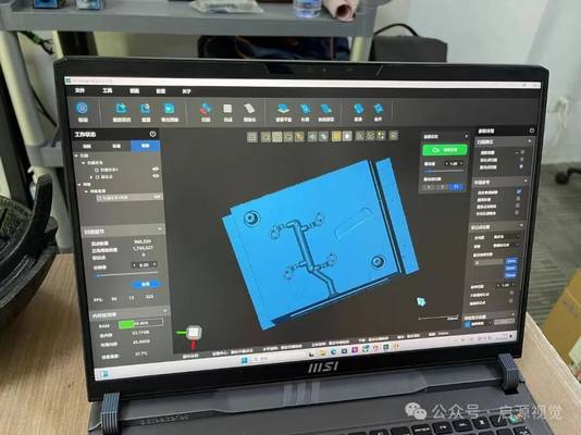
A workflow that actually solves mold corner inspection starts with defining where the corners are and what level of coverage they need. The most practical approach is to walk the tool with the scanner in live preview mode, checking the real-time point cloud on the display to confirm that each corner is filling in from at least two approach angles.
If a corner sits behind an undercut or a lifter, the scan path might need a third pass with the scanner rolled 90 degrees to capture the short side. The operator can mark the scan segments in the software so that the corner data is grouped for later analysis.
Once the point cloud covers the corner regions, the data pipeline moves to alignment, mesh generation, and CAD comparison. For a multi-cavity mold, the same corner feature across all cavities can be inspected against the same nominal, and the results can be plotted side by side. This turns the corner inspection from a one-at-a-time event into a tool health report.
If cavity 3 shows progressive wear in the gate corner while cavity 1 remains stable, the toolroom can schedule a preventive insert swap before the next production run.
The final step is documentation. The inspection report for a mold corner should include the cross-section profile at the worst deviation point, the color map of the full corner region, and a trend chart if the mold has been scanned over multiple cycles. INSVISION provides scan-to-CAD deviation analysis software that outputs these reports directly.
The data is traceable to the certified calibration of the scanner, which is backed by INSVISION’s CNAS-accredited metrology validation and ISO 9001 quality system. The result is a corner inspection that can be used for both in-house tool maintenance and customer-facing quality documentation.
Where This Changes the Toolroom Timeline
The traditional alternative to 3D scanning a mold corner is to section the tool or take a silicone cast and measure the cast on a comparator. Sectioning destroys the tool. Casting introduces its own shrinkage uncertainty and takes hours. Neither method is practical for a mold that is scheduled to run again in the next shift.
A handheld 3D scanner changes the equation: the mold can be scanned on the bench, in the press with the tool open, or at the maintenance crib without breaking setup.
The time savings compound when the tool is large. A bumper mold with twenty deep ribs, each with a 0.5-millimeter corner radius at the rib base, represents hundreds of individual corner features. Measuring each one with a radius gauge and a flashlight is slow and inconsistent.
Scanning the same mold with the AlphaScan can capture the entire rib geometry in a single session, and the corner analysis can be run offline while the tool goes back into production. The inspection data becomes a digital record of the mold’s condition at a specific cycle count, which is the foundation of predictive maintenance.
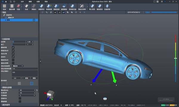
The capability that closes the argument is repeatability. A mold corner that scans to the same deviation result across three separate operators and two different shifts is data the toolroom can trust. INSVISION’s metrology-grade hardware and software are designed to deliver that consistency, with the certifications to support it.
For mold builders and molders who have been living with incomplete corner data, the gap is not in the inspection technology itself — it is in the decision to stop treating mold corners as inaccessible and start measuring them as a standard part of the tool condition workflow.
Hangzhou Insvision Technology Co.,Ltd.
Address: Building 1, No. 1399 Liangmu Road, Yuhang District, Hangzhou, Zhejiang 311121, China