

3D Scanning Point Spacing
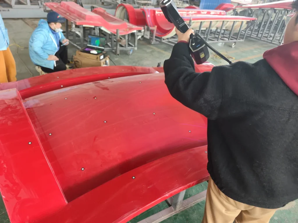
3D scanning point spacing, also referred to as point pitch or point distance, is the linear distance between adjacent discrete 3D coordinate points in a point cloud generated by a 3D scanning system.
Definition
3D scanning point spacing, also referred to as point pitch or point distance, is the linear distance between adjacent discrete 3D coordinate points in a point cloud generated by a 3D scanning system. It is a primary quantitative measure of point cloud density, and directly influences the level of surface detail that can be resolved from captured scan data. As a core performance and configuration parameter, it is used across industrial 3D scanning workflows including reverse engineering, dimensional inspection, and 3D modeling.
How It Works
When a 3D scanning system captures surface geometry, it samples the target object’s surface at discrete intervals to generate individual 3D coordinate points. The resulting point spacing is determined by a combination of hardware configuration, operating conditions, and software settings. Key influencing factors include the resolution of the scanner’s imaging sensors, the density of projected structured light patterns or laser lines, the working distance between the scanner and target object, the size of the scan field of view, and user-selected scan resolution modes (e.g., fine, standard, large-area). Point spacing is typically not uniform across an entire scan: points on surfaces farther from the scanner, or on highly curved or tilted surfaces, will have larger spacing than points on surfaces closer to the scanner or aligned perpendicular to the scanner’s optical axis. Many industrial 3D scanning systems allow users to adjust nominal point spacing prior to capture to balance detail requirements and data processing overhead.
Key Parameters and Criteria
Point spacing is evaluated alongside 3D scanning accuracy to ensure data is fit for intended use. The following core parameters are used to quantify and validate point spacing performance:
| Parameter | Meaning | Judgment Method |
|---|---|---|
| Nominal Point Spacing | The user-specified or factory-configured target distance between adjacent points, selected prior to scan capture via scanner software or mode settings | Cross-reference selected scan mode specifications with pre-scan software previews of expected point density |
| Actual Average Point Spacing | The measured mean distance between all valid adjacent point pairs across a captured point cloud, adjusted for working distance and object geometry | Calculate the average distance across 100+ random adjacent point pairs in point cloud processing software, excluding outlier points and scan edge artifacts |
| Point Spacing Uniformity | The degree of variance in point spacing across the full scanned surface, impacted by object tilt, surface reflectivity, and distance from the scanner | Compare point spacing measurements across 5+ distinct regions of a calibrated flat test panel; calculate the standard deviation of measured values to quantify uniformity |
| Feature Capture Threshold | The smallest surface feature (e.g., engraving, edge radius, hole diameter) that can be reliably resolved and measured from the point cloud, which scales proportionally with point spacing | Verify the visibility and dimensional accuracy of calibrated test artifacts with known feature sizes relative to measured average point spacing |
Suitable and Unsuitable Scenarios
Suitable Scenarios
- Fine detail capture for small industrial parts, mold textures, or micro-component inspection, where small point spacing (high density) is required to resolve sub-millimeter features.
- Reverse engineering of complex free-form surfaces (e.g., automotive interior panels, aerospace turbine blades), where sufficient point density is required to generate accurate continuous surface models.
- Large-area scanning of full vehicle bodies or large tooling, where larger point spacing reduces file size and processing time while retaining sufficient geometric data for dimensional validation.
Unsuitable Scenarios
- Use of excessively small point spacing for large, low-complexity objects (e.g., flat sheet metal panels), which creates unnecessarily large file sizes and extended processing times with no measurable improvement in data utility.
- Use of excessively large point spacing for metrology-grade inspection of tight-tolerance features (e.g., small hole positions, edge breaks), which leads to under-sampling and inaccurate dimensional readings.
- Scanning of unprocessed transparent or highly reflective surfaces, where uneven sampling can create inconsistent point spacing that distorts surface geometry regardless of nominal spacing settings.
Common Misconceptions
- Misconception: Smaller point spacing always equals higher scan quality. <br> Correction: Point spacing measures data density, not measurement accuracy. A high-density point cloud with high measurement error is less useful for industrial metrology than a lower-density cloud with consistent, verified accuracy.
- Misconception: Nominal point spacing is uniform across the entire scanned volume. <br> Correction: Point spacing increases with distance from the scanner, and may vary on curved or tilted surfaces, so actual average point spacing is a more reliable performance metric than nominal values.
- Misconception: Point spacing is a fixed hardware specification of a 3D scanner. <br> Correction: Most industrial 3D scanners allow adjustment of point spacing via scan mode settings, working distance modifications, or software resolution tuning, making it a configurable parameter rather than a fixed hardware property.
- Misconception: Point spacing is the only metric that determines detail capture capability. <br> Correction: Detail capture also depends on scanner accuracy, optical resolution, and surface sampling consistency. Two scanners with identical nominal point spacing may have vastly different detail capture performance if their accuracy or sampling uniformity differs.
Related Concepts
- Point Cloud: The collection of discrete 3D coordinate points generated by 3D scanning, for which point spacing is the primary density metric.
- 3D Scanner Accuracy: The degree of closeness of a scanned point’s coordinates to its true physical value, an independent parameter evaluated alongside point spacing for metrology applications.
- Scan Resolution: A broad term describing the level of surface detail a 3D scanner can capture, for which point spacing is the primary quantitative measure.
- GD&T Inspection: A dimensional quality control workflow that relies on appropriate point spacing to reliably verify geometric tolerances on manufactured parts.
- Point Cloud Downsampling: A post-processing step that reduces point cloud density by increasing effective point spacing to reduce file size and speed up processing.
FAQ
What is the relationship between point spacing and 3D scan accuracy?
Point spacing and accuracy are independent but complementary parameters. Point spacing describes the density of sampled surface points, while accuracy describes how close each point’s measured coordinates are to the true physical surface position. A small point spacing (high density) does not guarantee high accuracy, and high accuracy with overly large point spacing may fail to capture small critical features.
Can point spacing be reduced (density increased) after a scan is completed?
No. Point spacing is determined at the time of data capture by scanner settings, working distance, and optical configuration. Post-processing software can downsample a point cloud to increase effective point spacing (reduce density), but cannot add new points or reduce spacing to capture detail that was not sampled during scanning.
How do I select the appropriate point spacing for my application?
The appropriate point spacing depends on the size of the smallest feature you need to capture, the required measurement tolerance, and acceptable file size and processing time. As a general guideline, point spacing should be at least 3 to 5 times smaller than the smallest feature or tolerance threshold to ensure reliable measurement and feature resolution.
Does point spacing vary across different 3D scanning technologies?
Yes. Structured light, handheld laser, photogrammetry, and automated 3D scanning systems have different base point spacing ranges, with configurable settings to adjust spacing across use cases. For example, handheld scanners typically offer a wider range of adjustable point spacing to accommodate both small-part fine scanning and large-object wide-area capture, while fixed-position structured light systems may have more consistent spacing across their fixed working volume.
Summary
3D scanning point spacing is a core configurable parameter that defines the distance between adjacent points in a captured point cloud, directly impacting data density, detail capture capability, and workflow efficiency. It is evaluated alongside accuracy and uniformity to ensure scan data meets the requirements of industrial applications ranging from reverse engineering to metrology-grade quality inspection. Appropriate selection of point spacing based on specific application needs balances measurement reliability, data storage requirements, and processing speed.
- What Is 3D Scanning? Principles, Workflow, and Industrial Applications 3D scanning is a digital measurement technology that converts the surface geometry of physical objects into 3D data. This entry covers its working principles, core parameters, industrial use cases, common misconceptions, and related technical…
- What Is a 3D Scanner? Types, Parameters, and Selection Criteria A 3D scanner captures three-dimensional surface data from physical objects and converts geometry, dimensions, and features into digital data for inspection, reverse engineering, and modeling.
- What Is 3D Scanning Accuracy? Accuracy, Repeatability, and Resolution Explained 3D scanning accuracy describes how closely scan data matches an object's actual geometry and dimensions. It is assessed through local accuracy, volumetric accuracy, stitching accuracy, repeatability, and resolution.
- What Is Point Cloud Data? Point Clouds, Meshes, and CAD Models in 3D Scanning Point cloud data is an important raw data format in 3D scanning. It consists of discrete 3D coordinate points that describe object surface geometry and support inspection, reverse engineering, modeling, and archiving.
Hangzhou Insvision Technology Co., Ltd.
Address: Building 1, No. 1399 Liangmu Road, Yuhang District, Hangzhou, Zhejiang 311121, China
Copyright © Hangzhou Insvision Technology Co., Ltd. All rights reserved.
Copyright © Hangzhou Insvision Technology Co., Ltd. All rights reserved.