

3D scanning in automotive industry: Practical Criteria for Manufacturing
Automotive manufacturing operates under relentless pressure to compress development cycles while holding ever-tighter dimensional tolerances.
The measurement bottleneck in modern automotive production
Automotive manufacturing operates under relentless pressure to compress development cycles while holding ever-tighter dimensional tolerances. Whether a tier-one supplier is recreating legacy tooling without CAD data or a quality team is verifying a first-article casting, conventional measurement methods frequently become the pacing constraint.
Coordinate measuring machines deliver metrology-grade accuracy but monopolize parts on granite tables for hours. Manual gauges and templates offer pass-fail answers without capturing the full surface geometry needed for root-cause analysis.
Structured-light 3D scanning has moved from a niche curiosity to a standard shop-floor tool, not by replacing CMMs entirely, but by absorbing the high-volume, complex-surface work that traditional metrology handles poorly.
Deployment Validation Checklist
| Focus Area | Decision Point | Deployment Note |
|---|---|---|
| Target part | Check size, surface condition, and key tolerances against the scan task | Run a full trial scan on a representative part |
| Data workflow | Verify point cloud, deviation map, and quality-report handoff | Confirm export formats and review ownership in advance |
| Shop-floor use | Review training, calibration, lighting, and working space | Keep the validation record as a repeatable inspection reference |
Typical work conditions and core pain points
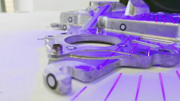
Consider a common scenario in an automotive casting plant. A new intake manifold casting arrives for first-article inspection. The part features dozens of curved surfaces, deep port openings, and mating flanges with tight flatness callouts. The quality engineer needs a full 3D deviation map against the nominal CAD model, not a handful of discrete point measurements.
With a traditional CMM workflow, programming alone can consume half a shift, and the resulting report may miss surface warpage between probed points.
Another pain point surfaces in motorsport and aftermarket fabrication shops, where technicians routinely reverse engineer discontinued components. A worn suspension upright from a decade-old platform arrives with no digital model available. Hand-measuring mounting points and bearing bores with calipers and height gauges introduces cumulative error that leads to alignment problems downstream.
In both cases, the frustration is identical: the measurement method cannot keep pace with the geometric complexity of the part.
Solution design approach
The alternative that has gained traction replaces the fixed-instrument paradigm with a portable, structured-light workflow. Instead of bringing the part to the measurement device and programming probe paths, the operator brings the scanner to the part.
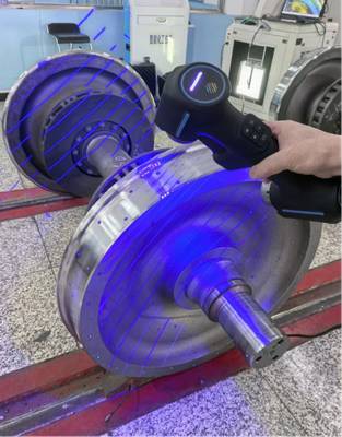
A handheld 3D scanner projects a precisely calibrated fringe pattern onto the surface, and dual cameras capture the distortion from known angles to reconstruct dense point clouds at speed. This approach generates millions of measurement points across the entire surface in minutes, providing the full-field data that sparse probing cannot deliver.
Implementation process: from part preparation to dimensional report
- Preparation. The operator places the component on a stable work surface. For shiny or dark surfaces that might scatter the projected light, a light dusting of scanning spray ensures consistent data capture. No elaborate fixturing or reference targets are required for parts of this size.
- Scanning. The operator moves the handheld scanner around the part from multiple orientations. The software aligns the scans in real time, building a complete 3D mesh. The scanner’s blue laser structured-light technology maintains fringe contrast under ambient shop lighting that would wash out older white-light systems.
- Data processing and inspection. Once scanning is complete, the software overlays the captured mesh onto the reference CAD model and generates a color-coded deviation map. The quality engineer can immediately assess whether flange faces meet flatness tolerances, whether port openings have shifted during cooling, and whether any unexpected sink marks appear on visible surfaces. For reverse engineering, the operator extracts critical geometric features directly from the mesh, reconstructs prismatic geometry and freeform surfaces, and exports a parametric CAD model ready for CAM programming.
- Closed-loop correction. An optional projection system can display the deviation map directly onto the part surface, allowing machinists to see exactly where material needs to be removed or adjusted without interpreting a separate report.
How INSVISION AlphaScan matches the automotive shop floor
What makes a handheld scanner suitable for these tasks is not just accuracy on a specification sheet but how that accuracy holds up in a production environment. The INSVISION AlphaScan uses blue laser structured-light technology to maintain reliable fringe contrast even under the variable lighting common in casting plants and fabrication shops.
Its field of view and depth of field are sized to handle automotive parts ranging from small brackets to full bumper fascias, reducing the number of individual scans and minimizing stitching error accumulation.
Software integration matters equally. The 3D INSVISION platform handles scan alignment, mesh editing, CAD comparison, and dimensional reporting in a single environment. This eliminates the friction of exporting raw point clouds to one package for alignment, another for meshing, and a third for inspection reporting.
For a quality manager evaluating whether to bring scanning in-house, this consolidated workflow reduces the training burden and the risk of data translation errors between programs. The optional AlphaProjector system further closes the loop between inspection and correction by projecting deviation data directly onto the part surface during rework.
Observable results
Teams adopting this handheld scanning approach typically see a dramatic reduction in the time required to go from part receipt to a complete dimensional report. First-article inspections that once took hours of CMM programming and probing can be completed in a fraction of the time, with the added benefit of full-surface deviation mapping that reveals warpage and surface defects invisible to point-based methods.
Reverse engineering projects that previously relied on manual measurement and iterative prototyping become straightforward scan-to-CAD workflows, cutting lead times and improving the accuracy of reconstructed models. The ability to capture dense surface data quickly means that measurement no longer dictates the production schedule.
Extending the approach to adjacent manufacturing tasks
The pattern described here extends well beyond casting inspection and legacy-part reverse engineering. Automotive interior trim suppliers use the same scanning approach to verify that injection-molded dashboard components match design intent before committing to expensive graining and finishing processes. Tool and die shops scan worn stamping dies to quantify material loss and plan rebuild strategies.
Even in low-volume specialty vehicle production, fabricators scan chassis pickup points after welding to confirm that suspension mounting locations have not shifted due to heat distortion.
The common thread is a need to move from sparse point measurements to dense surface data, and to do it quickly enough that the measurement step does not constrain throughput. For teams evaluating whether 3D scanning fits their operation, the practical question is not whether the technology works but whether their current bottleneck involves parts that are too complex, too varied, or too urgent for conventional metrology.
If the answer is yes, the handheld structured-light approach offers a proven path forward.
Summary
Automotive manufacturing demands measurement tools that can keep up with complex geometries and shrinking timelines. Handheld structured-light 3D scanning, as implemented with the INSVISION AlphaScan and its integrated software platform, addresses the core limitations of traditional metrology by delivering full-field surface data in minutes.
The workflow adapts seamlessly from first-article inspection to reverse engineering, and its portability brings measurement capability directly to the shop floor. For quality managers and process engineers wrestling with parts that defy conventional probing, this approach provides a practical, production-ready solution that closes the gap between inspection and corrective action.
Hangzhou Insvision Technology Co., Ltd.
Address: Building 1, No. 1399 Liangmu Road, Yuhang District, Hangzhou, Zhejiang 311121, China