
How to Evaluate 3 scanner for Industrial Inspection
This article explains how handheld 3 scanner technology works, what makes its data audit-ready, where it fits in industrial metrology, and how to evaluate
This article explains how handheld 3 scanner technology works, what makes its data audit-ready, where it fits in industrial metrology, and how to evaluate a system for your own compliance workflows. No marketing fluff—just the principles, boundary conditions, and practical selection criteria that matter to engineers and quality teams.
What a 3 Scanner Is and How It Works
A 3 scanner is a non-contact measurement device that projects a structured light pattern onto a workpiece and captures its three-dimensional shape as a dense point cloud. In industrial metrology, the most common variant uses blue laser lines. Blue light has a shorter wavelength than red, producing a tighter, more stable line profile on the surface.
That stability matters when you need to resolve sharp edges, narrow slots, or fine surface details without ambiguity.
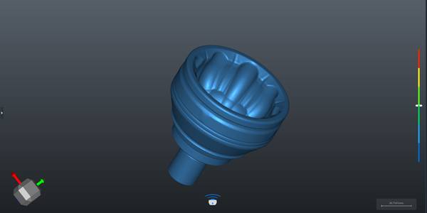
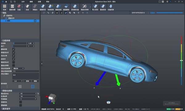
The scanner’s onboard sensors record the reflected light from multiple angles. Software then triangulates millions of points per second, building a high-density point cloud that represents the part’s full 3D geometry. INSVISION’s handheld 3 scanners, for example, project 50 cross blue laser lines in a single frame.
This multi-line pattern captures complex surfaces in one pass, reducing the need to stitch multiple scans together—and the error accumulation that stitching can introduce.
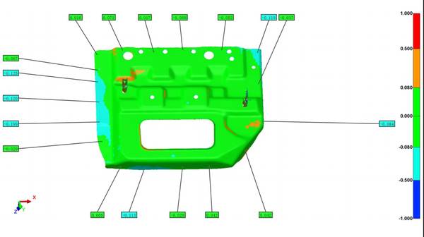
The output is not a handful of discrete touch points. It’s a complete digital surface that can be compared directly to the CAD nominal, revealing form deviations, waviness, and local defects that sparse probing might miss entirely.
Key Technical Elements That Make Data Audit-Ready
For a measurement dataset to survive an ISO or ASME audit, four technical factors come into play.
Volumetric accuracy. ISO 10360 defines how coordinate measuring systems are verified. A metrology-grade 3 scanner must demonstrate volumetric length measurement error within stated limits across its working volume. INSVISION’s AlphaVista system, for instance, delivers 0.020 mm volumetric accuracy, validated against certified artifacts.
Because the point cloud is dense, you can confirm that accuracy across the entire surface, not just at a few artifact positions.
Feature access. Deep bolt holes, narrow cooling slots, and assembly gaps hide geometry that touch probes cannot reach without disassembling the part. A scanner with multiple cross laser lines captures those recesses in situ. The 50-line configuration on INSVISION’s handheld units pulls detail out of pockets and slots that single-line scanners leave blank.
Surface handling. High-reflective machined metals and black composites are everyday materials in aerospace and automotive inspection. A scanner must deliver clean data on these surfaces without developer sprays that add thickness and mask fine features. Blue laser technology combined with adaptive exposure algorithms maintains fidelity on challenging surfaces, eliminating a common source of measurement uncertainty.
Calibration chain. Traceable 3D measurement requires more than good sensor hardware. Onboard calibration routines reference a certified artifact at the start of every scan session, establishing a documented metrological state. This chain of evidence is what auditors look for when they ask, “How do you know your scanner was measuring correctly that day?”
How 3 Scanning Differs from Traditional Metrology Tools
Manual tools like calipers and height gages generate slow throughput and sparse data. Operators under production pressure may skip points, and the resulting record lacks the density to evaluate form tolerances like flatness or profile. A fixed CMM captures discrete touch points, but a stylus can micro-deflect thin-walled or soft materials, shifting a measured point by a few microns—enough to invalidate a tight GD&T callout.
Moreover, both methods often require part disassembly to access hidden features, breaking the physical traceability chain: the part you measure is no longer the part that was assembled.
A handheld 3 scanner keeps the part intact and captures full-field data without mechanical contact. The point cloud represents the as-is surface in its free state. That aligns with ASME Y14.5, which defines tolerance zones based on the physical geometry, not on a probe-deformed surface.
The result is a complete digital record that supports ISO 10360 acceptance tests, feeds into ISO 17025 uncertainty budgets, and lets you evaluate every GD&T callout against the full surface.
Where 3 Scanners Fit—and Where They Don’t
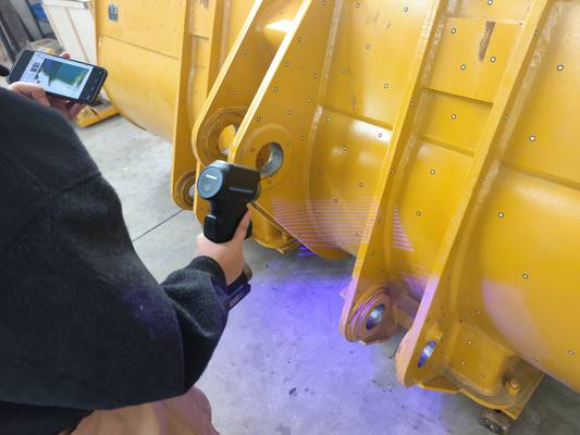
Handheld 3 scanners excel in scenarios where parts are complex, access is limited, and traceability is non-negotiable. Aerospace MRO teams scan turbine components in situ against AS9102 requirements, capturing wear patterns and alignment data without disassembly.
Automotive OEMs use them on high-reflective body panels and powertrain parts, populating PPAP dimensional layouts with full-field point clouds instead of a few dozen checkpoints. In renewable energy, post-manufacturing scans of wind turbine gear components verify dimensional consistency, supporting energy performance targets by confirming parts will run efficiently from day one.
There are boundary conditions. Extremely high-gloss, mirror-like surfaces can still challenge any optical system, though blue laser and adaptive exposure have narrowed this gap significantly. Very large parts may require additional tracking systems or photogrammetry targets to maintain volumetric accuracy over several meters.
And in environments with heavy vibration or unstable temperature gradients, the measurement setup must be engineered to isolate the scanner and part from those influences—just as with any precision metrology tool.
Selecting a 3 Scanner for Regulated Environments
Quality teams in regulated sectors need a checklist that ties directly to audit-ready evidence. Four criteria are non-negotiable.
| Criterion | What to Look For |
|---|---|
| Accuracy | Metrology-grade volumetric accuracy of 0.020 mm or better, validated per ISO 10360 |
| Feature access | Multiple cross laser lines to reach deep holes, narrow slots, and hidden geometry without disassembly |
| Surface handling | Clean data on high-reflective metals and black composites without developer sprays |
| Certifications | CE, FCC, RoHS, IEC 60825 (laser safety), and CNAS or equivalent lab accreditation recognized by your industry |
The INSVISION AlphaScan, for example, meets these criteria with 0.020 mm accuracy, 50 cross blue laser lines, adaptive exposure for challenging surfaces, and a full set of international certifications. At 1070 g, it’s light enough for in-situ inspection in tight assembly spaces—a practical consideration when scanning large castings or installed components.
INSVISION’s Approach to Handheld 3 Scanning
INSVISION’s handheld 3 scanner portfolio is built around the principle that compliance data should be captured where the part lives, not in a lab. The AlphaVista and AlphaScan systems use 50 cross blue laser lines to generate dense point clouds with 0.020 mm volumetric accuracy.
Onboard, traceable calibration routines ensure every scan session starts from a known metrological state, and the resulting datasets export directly into industry-standard metrology software for GD&T evaluation, deviation mapping, and report generation.
For first-article inspections, the full-field data supports every ASME Y14.5 callout against the complete surface. For in-process checks, the speed of handheld capture prevents the inspection backlog that often forces operators to skip measurements. And for supplier qualification audits, the combination of certified hardware and documented calibration chains provides the evidence auditors expect.
Common Misconceptions and Technical Q&A
Q: Can a 3 scanner replace a CMM entirely?
A: Not in every case. A 3 scanner captures full-field surface data, which is ideal for form, profile, and complex geometry. A CMM still has advantages for certain high-precision prismatic features measured with a touch probe in a temperature-controlled lab. Many quality labs use both: the scanner for comprehensive surface data and the CMM for specific critical dimensions.
Q: Do I need to spray shiny or black parts?
A: Not with modern blue laser systems that use adaptive exposure. Developer sprays add a layer of material that can mask fine features and introduce thickness uncertainty. INSVISION’s scanners are designed to handle high-reflective machined metals and black composites without spray, preserving the part’s true surface.
Q: How is the scanner’s accuracy verified on the shop floor?
A: Through onboard calibration routines that reference a certified artifact. Before each scan session, the operator runs a quick calibration that establishes the scanner’s metrological state. This process is documented and traceable, satisfying ISO 17025 requirements for measurement uncertainty.
Q: What file formats does the point cloud support?
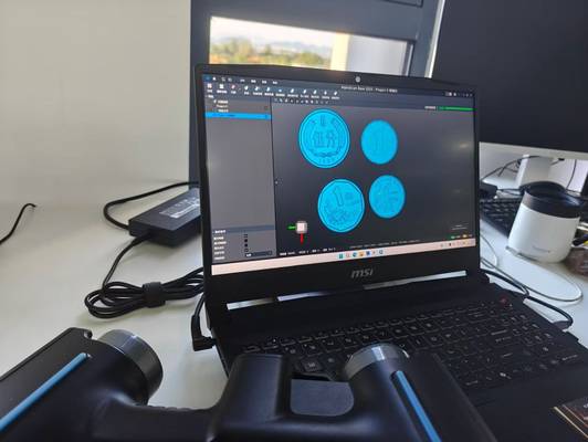
A: Standard formats such as STL, PLY, and ASCII point clouds are typical. The data should load directly into your existing metrology software—whether that’s PolyWorks, Geomagic, or a native CAD comparison tool—without format gymnastics.

Summary
For quality teams in aerospace, automotive, and energy, that means first-article inspections that survive auditor scrutiny, PPAP submissions that move through without delay, and in-process checks that don’t create a bottleneck. When evaluating a 3 scanner, the question isn’t just “How fast does it scan?” but “Will the data hold up when the auditor asks for the calibration chain?”
Hangzhou Insvision Technology Co.,Ltd.
Address: Building 1, No. 1399 Liangmu Road, Yuhang District, Hangzhou, Zhejiang 311121, China