

What Is Reverse Engineering? The Role of 3D Scanning in Reverse Modeling
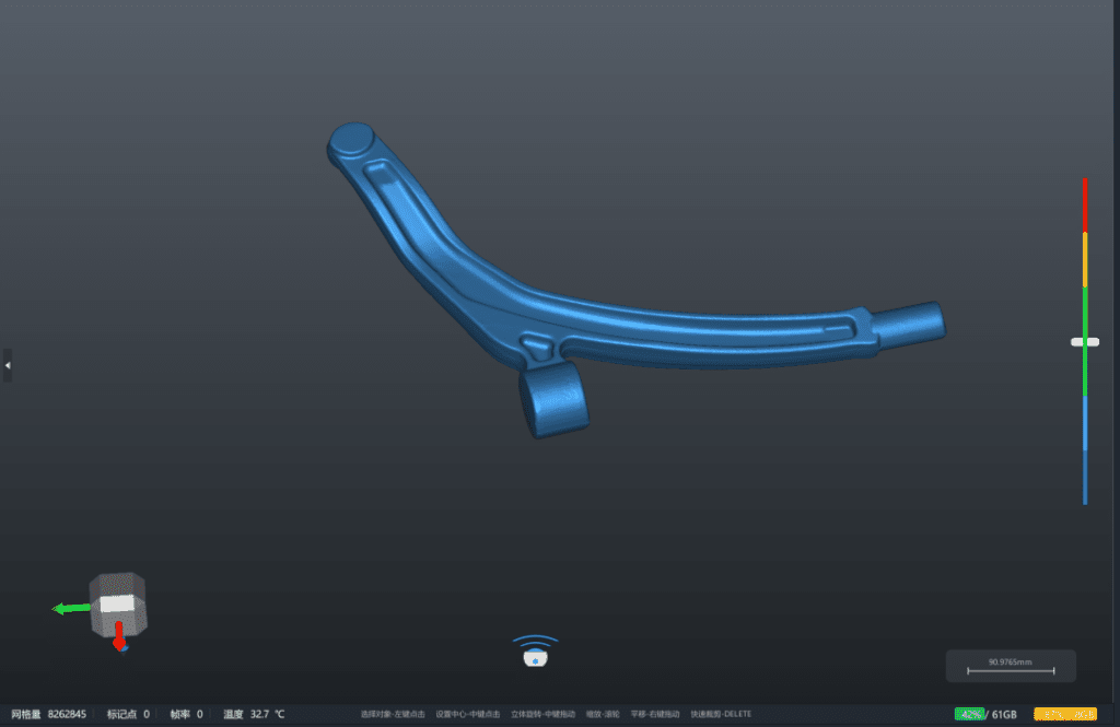
Reverse engineering uses 3D scanning and digital modeling to convert existing physical workpieces into editable CAD models for product modification, mold development, inspection, and additive manufacturing.
Definition
Reverse engineering (in the industrial sector) is a technical system that acquires measured geometric data from existing physical workpieces via 3D digital methods, processes the data to reconstruct editable computer-aided design (CAD) models, and is applied to workflows including product modification, mold development, quality validation, and additive manufacturing. It complements forward engineering (the workflow from requirements gathering to design to production), and is an important technique for digitizing physical assets in industrial workflows.
Working Principle
The implementation process of industrial reverse engineering is divided into four main stages, each of which can be configured with different hardware architectures (such as single/multi-camera, single/multi-projector, optical tracking systems, etc.) based on project requirements:
- Data Acquisition: Use non-contact (such as laser, blue light scanning) or contact measurement equipment to obtain 3D point cloud data of the workpiece surface; for large-format or complex-structure workpieces, multi-view stitching or optical tracking technology can be used to expand the acquisition range.
- Data Preprocessing: Perform operations including denoising, hole filling, multi-frame stitching, and coordinate alignment on raw point cloud data, remove redundant data, and generate a complete point cloud model that conforms to spatial logic.
- Feature Reconstruction: Segment the preprocessed point cloud into domain regions (including identification and separation of geometric features such as curved surfaces, hole positions, and chamfers), and generate parameterized geometric features via surface fitting algorithms.
- CAD Conversion and Validation: Convert reconstructed geometric features into editable CAD formats, and use deviation analysis tools to verify the consistency of accuracy between the digital model and the original physical workpiece.
Key Parameters and Evaluation Criteria
The practical performance of reverse engineering depends on the following quantifiable parameters, and evaluation methods should follow relevant metrology requirements, project acceptance criteria, or enterprise quality rules:
| Parameter | Definition | Evaluation Method |
|---|---|---|
| Scanning Accuracy | The degree of deviation between scanned point cloud data and the true geometric dimensions of the physical workpiece | Use calibrated standard gauge blocks or standard spheres as benchmarks, and calculate the absolute deviation between scanned data and the benchmark post-scanning |
| Point Cloud Density | The number of point cloud points per unit sampling area, which directly determines detail reproduction capability | Count the number of points in a unit area via 3D data processing software, measured in points per square centimeter |
| Data Alignment Accuracy | The overall spatial deviation after multi-frame point cloud stitching or multi-source data fusion | Use common marker points or inherent geometric features as alignment benchmarks, and calculate the root mean square error (RMSE) post-stitching |
| Surface Fitting Error | The local deviation between the reconstructed CAD surface and original point cloud data | Use deviation analysis tools to generate a color map, and count the maximum deviation, average deviation, and deviation distribution range |
| Format Compatibility | The number of industrial-grade 3D data formats supported for import and export | Verify the format support list of the data processing software, which must cover mainstream CAD formats (such as STEP, IGES, STL, etc.) |
Applicable and Inapplicable Scenarios
Applicable Scenarios
- Industrial product modification design (such as automobile steering knuckles, motorcycle exterior sheet metal parts, new energy vehicle battery modules);
- Reverse mold development (such as digital reconstruction of highly reflective metal molds);
- Physical digitization preprocessing prior to additive manufacturing;
- Replication of industrial workpieces with missing original CAD data;
- Detailed digital modeling for industrial-grade cultural heritage restoration.
Inapplicable Scenarios
- Non-industrial scenarios such as human body scanning and medical image diagnosis;
- Reverse engineering of small civilian objects with no clear industrial application requirements.
Common Misconceptions
- Reverse engineering is equivalent to "raw point cloud capture": Raw point cloud capture only refers to the stage of collecting original scan data, while reverse engineering covers the full workflow of point cloud preprocessing, feature extraction, surface fitting, editable CAD model reconstruction, and accuracy validation, with its main function being the generation of digital assets suitable for production and design.
- Only scanning accuracy requires attention: The final usability of reverse engineering outputs also depends on parameters including data alignment accuracy, surface fitting quality, and format compatibility. High scanning accuracy alone does not guarantee the final model meets industrial requirements.
- Reverse engineering can be performed on all physical objects: Limited by technical principles, objects that are excessively small, have micro-sized holes, or are highly reflective without surface pretreatment may not produce valid data, and are not within the applicable scope.
- Reverse engineering is only used for product replication: In addition to workpiece replication, reverse engineering can also be applied to product optimization, quality validation, process improvement and other scenarios, making it an important supplementary method for forward engineering.
Related Concepts
- 3D scanning: A common data acquisition method for reverse engineering, divided into contact and non-contact categories. Non-contact types (laser, blue light) are widely used due to their high efficiency and non-damaging properties.
- Point cloud processing: The preprocessing workflow for raw scanned point clouds, including denoising, stitching, and hole filling, which is the foundational stage of reverse engineering.
- Forward engineering: The traditional product development workflow that starts from product requirements, followed by CAD modeling, process design, and manufacturing, which complements reverse engineering.
- Additive manufacturing: A common application use case for reverse engineering, which allows directly using reconstructed CAD models for 3D printing production.
- Metrology-grade inspection: A technical method used to verify the accuracy of reverse-engineered models, helping verify whether models meet project tolerance requirements via deviation analysis.
Frequently Asked Questions
Does reverse engineering require surface pretreatment of scanned objects?
Answer: It depends on the surface characteristics of the scanned object and the performance of the acquisition equipment. For example, highly reflective metal molds usually require spraying a thin developer to reduce specular reflection and improve data acquisition accuracy; low-reflective materials such as matte plastic and wood generally do not require pretreatment.
Can models generated by reverse engineering be directly used for industrial production?
Answer: They require accuracy validation and optimization first. Raw data obtained solely via point cloud acquisition cannot be used directly. Processes including feature extraction, surface fitting, and GD&T tolerance inspection must be completed first. Only editable CAD models that pass validation can be used for production workflows such as mold design and additive manufacturing.
What are the size limits for reverse engineering applications?
Answer: There is no fixed universal size threshold. The processable range depends on the scanning equipment's field of view, resolution, working distance, stitching method, the reflectivity of the tested surface, and the final model accuracy requirements. Large workpieces usually require multi-view stitching or global coordinate control; small precision parts require higher resolution and stricter calibration processes.
Can reverse engineering data be compared and validated with forward design data?
Answer: Yes. Using deviation analysis tools (such as built-in GD&T functions) in 3D data processing software, the reverse reconstructed model can be aligned with the original forward CAD data to generate a deviation color map and quantitative report, which can be used for product design validation and quality control.
Summary
Reverse engineering is a technical workflow that connects physical assets with digital design in industrial digitalization. It acquires measured geometric data of physical workpieces via 3D scanning, reconstructs editable CAD models through end-to-end processing, and provides digital support for scenarios including product modification, mold development, and additive manufacturing. During application, users should define applicable boundaries, prioritize key parameters, and avoid common misconceptions to ensure the industrial usability of reconstructed models.
- What Is 3D Scanning? Principles, Workflow, and Industrial Applications 3D scanning is a digital measurement technology that converts the surface geometry of physical objects into 3D data. This entry covers its working principles, core parameters, industrial use cases, common misconceptions, and related technical…
- What Is a 3D Scanner? Types, Parameters, and Selection Criteria A 3D scanner captures three-dimensional surface data from physical objects and converts geometry, dimensions, and features into digital data for inspection, reverse engineering, and modeling.
- What Is 3D Scanning Accuracy? Accuracy, Repeatability, and Resolution Explained 3D scanning accuracy describes how closely scan data matches an object's actual geometry and dimensions. It is assessed through local accuracy, volumetric accuracy, stitching accuracy, repeatability, and resolution.
- What Is Point Cloud Data? Point Clouds, Meshes, and CAD Models in 3D Scanning Point cloud data is an important raw data format in 3D scanning. It consists of discrete 3D coordinate points that describe object surface geometry and support inspection, reverse engineering, modeling, and archiving.
Hangzhou Insvision Technology Co., Ltd.
Address: Building 1, No. 1399 Liangmu Road, Yuhang District, Hangzhou, Zhejiang 311121, China
Copyright © Hangzhou Insvision Technology Co., Ltd. All rights reserved.
Copyright © Hangzhou Insvision Technology Co., Ltd. All rights reserved.