

What Is 3D Scanning Accuracy? Accuracy, Repeatability, and Resolution Explained
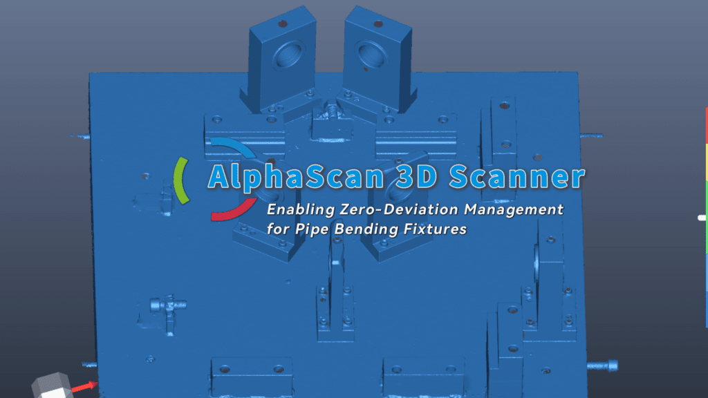
3D scanning accuracy describes how closely scan data matches an object's actual geometry and dimensions. It is assessed through local accuracy, volumetric accuracy, stitching accuracy, repeatability, and resolution.
Definition
3D scanning accuracy is a core performance metric that quantifies the degree of alignment between point cloud data and 3D models output by a 3D scanning device, and the actual geometric form and dimensions of the scanned object. It is the foundational basis for applying 3D scanning technology to use cases such as industrial 3D inspection and reverse engineering, and is typically expressed as quantifiable values such as length deviation or volume deviation. It can be divided into evaluation dimensions such as local accuracy and global accuracy based on application scenarios, to meet the measurement needs of objects ranging from small and medium-sized parts to large-scale components.
Accuracy Formation and Error Sources
3D scanning accuracy is formed across the full measurement workflow: device calibration, signal projection or imaging, point coordinate calculation, multi-view alignment, point cloud processing, and comparison with reference geometry. Each stage can introduce deviation. Surface reflectivity, transparency, temperature drift, vibration, scan distance, registration strategy, and post-processing settings can all affect the final result. Therefore, nominal accuracy should be understood as performance measured under specified test conditions, while actual project accuracy needs to be verified with the relevant workpiece, environment, and acceptance method.
Key Parameters and Evaluation Criteria
The evaluation of 3D scanning accuracy requires comprehensive judgment based on multiple parameters. The actual performance of all parameters is affected by factors including the surface material of the scanned object, ambient temperature and humidity, scanning distance, stitching method, and post-processing parameter settings. Nominal accuracy usually describes performance measured under specified test conditions and should be verified against the actual workpiece, environment, and acceptance method.
| Parameter | Definition | Evaluation Method |
|---|---|---|
| Single-scan accuracy | Also called local accuracy, refers to the maximum allowable deviation between scanned data and the actual dimensions of the scanned object within a single scan field of view. It is typically used for accuracy evaluation of small and medium-sized parts | Use metrology-grade gauge blocks or standard spheres as test artifacts, complete a single scan at the device’s optimal scanning distance, and compare the deviation between the measured value and the nominal value of the standard artifact |
| Volumetric accuracy | Refers to the overall dimensional deviation of scanned data within a specified measurement space. It is usually expressed in the form of "fixed deviation + incremental deviation per unit length", and is the core accuracy indicator for full-size measurement of large workpieces | Arrange multiple sets of metrology-grade standard scales or standard sphere groups evenly within the measurement space, measure the dimensions of standard artifacts at different positions after completing a full-range scan, and calculate the maximum deviation of all measurement results |
| Stitching accuracy | Refers to the deviation of overlapping features in adjacent fields of view or different scanning regions after multiple sets of scanned data are aligned and stitched. It directly affects the overall scanning accuracy of large-sized, complex-structured objects | Scan a standard artifact with common marker points or known features, compare the deviation between the scanned dimension and the actual dimension of the common features after completing multi-field stitching |
| Repeatability (Repeat Accuracy) | Refers to the consistency deviation of multiple scan results for the same scanned object under the same scanning conditions, and reflects the performance stability of the device | Re-scan the same metrology-grade standard artifact multiple times under the same environment and operation process, and calculate the standard deviation of multiple measurement results |
Applicable and Non-Applicable Scenarios
Applicable Scenarios
- Batch tolerance inspection of small and medium-sized parts, product dimension and deviation analysis in the industrial manufacturing field
- Full-size inspection of large components, full-vehicle scanning and deviation assessment in the aerospace and automotive fields
- GD&T verification of 3D printed parts, reverse engineering modeling
- Evaluation of uneven component wear, 3D model deviation visualization analysis in fields such as photovoltaic energy and energy equipment
Non-Applicable Scenarios
- Non-industrial civilian scenarios such as body scanning and facial scanning
- Medical imaging diagnostic applications
- High-precision scanning of highly reflective or fully transparent objects that have not undergone surface treatment
Common Misconceptions
- Higher nominal accuracy equals better real-world performance: Nominal accuracy is the optimal value obtained under standard laboratory conditions, and actual accuracy is greatly affected by scenario factors. If only high nominal accuracy is pursued while ignoring indicators such as volumetric accuracy and stitching stability, actual measurement requirements may not be met. For example, large workpiece measurement requires priority focus on volumetric accuracy rather than single-scan nominal accuracy.
- All application scenarios require the highest accuracy: Accuracy requirements vary significantly across different applications. For example, the accuracy requirement for reverse engineering modeling is usually lower than that for metrology-grade tolerance inspection. Blind pursuit of micron-level high accuracy will greatly increase scanning time, data storage and processing costs, resulting in unnecessary resource waste.
- Stitching accuracy has limited impact on overall results: Scanning large-sized objects requires stitching of dozens or even hundreds of scan datasets. Without global coordinate system control, minor errors from single scans will accumulate continuously as the number of stitching operations increases, eventually leading to out-of-tolerance overall dimensional deviation. Stitching accuracy is one of the core influencing factors for large-size scanning.
- Scanning speed is unrelated to accuracy: Increasing scanning rate generates more point cloud data per unit time. If the algorithm has insufficient noise filtering and feature recognition capabilities, it will lead to increased point cloud noise and feature recognition deviation, thereby reducing actual scanning accuracy. Matching high speed and high accuracy relies on the collaborative optimization of algorithms and hardware.
Related Concepts
- Cumulative error: Refers to the phenomenon where errors from individual measurements are superimposed as the measurement range expands and the number of stitching operations increases during multi-scan stitching and long-distance measurement. It is one of the main error sources for large-size scanning.
- Global coordinate system: Refers to a unified spatial reference system established via photogrammetry scales, global marker points, etc., which can align all scanned data to the same reference benchmark, effectively reducing stitching cumulative error.
- Point cloud denoising: A post-processing step that removes outlier points and noise points generated during the scanning process via algorithms. Reasonable denoising processing can effectively improve the actual accuracy of point cloud data.
- GD&T inspection: One of the core scenarios of industrial inspection, used to verify whether the shape and position errors of a scanned object meet design requirements, and has clear quantifiable requirements for 3D scanning accuracy.
Frequently Asked Questions
Why is there a difference between the nominal accuracy and actual in-use accuracy of 3D scanning?
Nominal accuracy is the optimal performance value of a device measured with standard test artifacts under standard laboratory conditions with constant temperature, constant humidity, and no vibration. In real-world usage scenarios, factors such as the surface material of the scanned object (such as highly reflective, semi-transparent, or light-absorbing materials), ambient temperature drift, vibration, scanning distance deviating from the optimal value, stitching method, and post-processing parameter settings will introduce additional errors. Therefore, there is usually a certain difference between actual in-use accuracy and the nominal value, and evaluation should be performed after completing calibration combined with the actual scenario.
Why can't single-scan accuracy be used as the only reference when measuring large workpieces?
The dimensions of large workpieces usually far exceed the field of view of a single scan, requiring full-size data acquisition via stitching of dozens or even hundreds of scans. If only single-scan accuracy is focused on, while volumetric accuracy and stitching error control are ignored, minor errors from individual scans will accumulate continuously as the scanning range expands, eventually leading to overall dimensional deviation exceeding the allowable range. Therefore, large workpiece measurement requires priority reference to the volumetric accuracy indicator, combined with a global coordinate system establishment scheme to reduce cumulative error.
Is micron-level accuracy suitable for all industrial inspection scenarios?
No. Micron-level accuracy is usually suitable for scenarios with extremely high accuracy requirements such as tolerance inspection of high-precision components and measurement of tiny features. For scenarios such as GD&T inspection of large components, reverse engineering modeling, and verification of ordinary 3D printed parts, excessively high accuracy requirements will greatly increase scanning time, data storage and processing costs, and instead reduce work efficiency. Users should select a matching accuracy level based on actual tolerance requirements.
How to verify the actual in-use accuracy of 3D scanning?
Metrology-grade standard artifacts (such as gauge blocks, standard spheres, calibration scales) can be used as test objects. Complete scanning under the actual usage environment and operation process, compare the scanned dimensional data with the nominal value of the standard artifact, and calculate the deviation value to obtain the actual in-use accuracy under the corresponding scenario. For large workpiece measurement scenarios, multiple sets of standard artifacts can be arranged evenly within the measurement space, and deviations at different positions can be measured separately to evaluate the accuracy performance of the entire space.
Summary
3D scanning accuracy is a core performance indicator for industrial 3D digitization applications, and its actual performance is jointly affected by multiple factors such as hardware design, algorithm optimization, scanning scenarios, and operation processes. When evaluating and selecting accuracy indicators, comprehensive judgment should be made based on the dimensional characteristics of the scanned object, application tolerance requirements, on-site environmental conditions, etc., to avoid blind pursuit of high nominal accuracy. At the same time, standardized calibration processes and reasonable coordinate system establishment schemes can effectively reduce error interference, and ensure that actual measurement accuracy meets the application requirements of multiple scenarios such as industrial inspection, reverse engineering, and digital modeling.
- What Is 3D Scanning? Principles, Workflow, and Industrial Applications 3D scanning is a digital measurement technology that converts the surface geometry of physical objects into 3D data. This entry covers its working principles, core parameters, industrial use cases, common misconceptions, and related technical…
- What Is a 3D Scanner? Types, Parameters, and Selection Criteria A 3D scanner captures three-dimensional surface data from physical objects and converts geometry, dimensions, and features into digital data for inspection, reverse engineering, and modeling.
- What Is Point Cloud Data? Point Clouds, Meshes, and CAD Models in 3D Scanning Point cloud data is an important raw data format in 3D scanning. It consists of discrete 3D coordinate points that describe object surface geometry and support inspection, reverse engineering, modeling, and archiving.
- What Is Reverse Engineering? The Role of 3D Scanning in Reverse Modeling Reverse engineering uses 3D scanning and digital modeling to convert existing physical workpieces into editable CAD models for product modification, mold development, inspection, and additive manufacturing.
Hangzhou Insvision Technology Co., Ltd.
Address: Building 1, No. 1399 Liangmu Road, Yuhang District, Hangzhou, Zhejiang 311121, China
Copyright © Hangzhou Insvision Technology Co., Ltd. All rights reserved.
Copyright © Hangzhou Insvision Technology Co., Ltd. All rights reserved.