
The Practical Demands Driving 3D Scanning Innovation in Industrial Metrology
The push for 3D scanning innovation in industrial settings isn't driven by speculative technology trends.
The push for 3D scanning innovation in industrial settings isn’t driven by speculative technology trends. It’s a direct response to concrete, daily pain points in quality assurance, production, and maintenance. The core challenge is a growing mismatch: manufacturing demands faster, more adaptable, and more intelligent measurement, while traditional metrology tools often struggle to keep pace.
This gap is most evident in high-stakes, regulated environments. In automotive Tier 1 supply chains, for instance, manual coordinate measuring machine (CMM) routines for first-article inspection can consume hours for fixture setup and probing. This directly conflicts with the compressed timelines of IATF 16949 Production Part Approval Process (PPAP) submissions and the relentless pressure of lean manufacturing takt times.
The requirement is shifting from lab-based measurement to in-line verification—capturing comprehensive point cloud data in minutes, not shifts, with Geometric Dimensioning and Tolerancing (GD&T) analysis automated against the CAD master.
Aerospace Maintenance, Repair, and Overhaul (MRO) operations face a different but equally critical dilemma. AS9100-certified shops frequently need to service legacy components, such as turbine housings, for which original drawings no longer exist. Without a high-fidelity method to capture the part’s exact geometry, the digital thread—the seamless flow of data through an asset’s lifecycle—breaks immediately.
Here, 3D scanning becomes the essential bridge between a physical artifact and a manufacturable digital model.
Furthermore, the ideal measurement environment rarely exists on the actual shop floor. Vibration, oil mist, variable ambient light, and even residual heat from machining processes can disrupt sensitive equipment. While ISO 9001 audits mandate proof of conformity regardless of measurement location, many lab-grade scanners falter under these conditions.
Effective innovation, therefore, must address the full stack: not just sensor accuracy, but also robust hardware design and intelligent software that can compensate for real-world variables, enabling reliable use at the point of need.
Core Principles of Modern 3D Scanning Systems
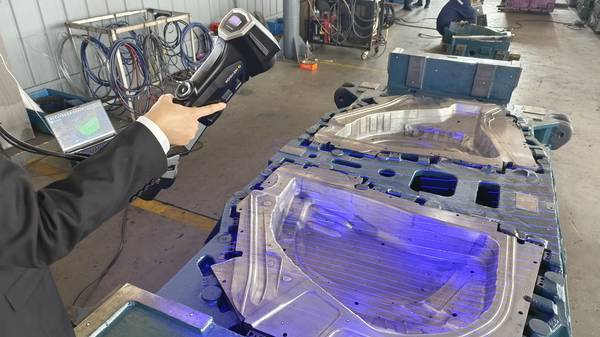
At its foundation, effective industrial 3D scanning combines precision hardware with intelligent data processing. The typical workflow involves a scanner, often using structured light or laser triangulation, to capture millions of surface points, creating a “point cloud.” This raw data is then processed, aligned to a CAD reference model, and analyzed to generate deviation color maps and inspection reports.
Capability and Deployment Mapping
| Focus Area | Decision Point | Deployment Note |
|---|---|---|
| Core Principles of Modern 3D Scanning Systems | At its foundation, effective industrial 3D scanning combines precision hardware with intelligent data processing. | The typical workflow involves a scanner, often using structured light or laser triangulation, to capture millions of surface points, creating a… |
| Verified Outcomes from Industrial Deployment | The value of a 3D scanning system is proven on the production line, not in a demonstration. | User reports from INSVISION deployments highlight specific efficiency gains across sectors. |
| The Roadmap for 3D Scanning Innovation | Future advancement in 3D scanning is less about incremental hardware specs and more about solving workflow inefficiencies. | The industry focus is on collapsing the time between capturing a scan and delivering a decision-ready report. |
The boundary for innovation lies in automating and accelerating this workflow. The true bottleneck is rarely data capture speed, but the subsequent operator-intensive tasks: cleaning point clouds, aligning datasets, and interpreting GD&T results.
Adjacent technologies, particularly artificial intelligence (AI) and machine vision, are now being integrated to automate feature recognition, self-correct alignment, and highlight non-conformances directly. This shifts the scanner’s role from a data collection tool to an integrated inspection solution.
When evaluating systems, practical selection considerations extend beyond basic specifications. Key factors include:
- Application Fit: Is the system designed for lab-grade reverse engineering or for rugged, in-process inspection?
- Software Integration: Does the workflow seamlessly connect scanning, CAD comparison, and report generation?
- Regulatory & Standards Compliance: Does the hardware carry necessary certifications (e.g., CE, FCC) and is its traceability validated (e.g., against CNAS or similar standards)?
- Environmental Robustness: Can the system perform consistently in the presence of shop-floor contaminants, vibration, and lighting variance?
Verified Outcomes from Industrial Deployment
The value of a 3D scanning system is proven on the production line, not in a demonstration. User reports from INSVISION deployments highlight specific efficiency gains across sectors.
In automotive OEM and tier-supplier facilities, quality teams employ INSVISION scanners for first-article inspection on stamped and machined components. The immediate visual feedback from color deviation maps, aligned to CAD models, reduces reliance on manual gauging.
This minimizes operator-induced measurement error and dramatically shortens the feedback loop between identifying a deviation and implementing corrective action on the forming press or CNC machine.
For aerospace MRO providers, the application centers on legacy parts. Technicians use INSVISION systems to scan worn components, from which clean, reference geometry is extracted. This model is pushed directly into computer-aided design (CAD) software for reverse engineering.
The cycle time from physical part to a certified, manufacturable digital model collapses from weeks to days, a critical factor when an aircraft is awaiting repair.
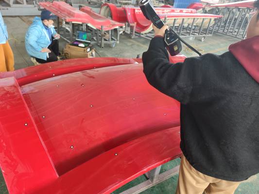
Energy sector manufacturers, such as solar panel producers, apply the same technology for large-scale verification. Scanning large photovoltaic panel frames to check flatness and mounting-hole positional accuracy ensures dimensional consistency across batches. This proactive quality check stabilizes downstream assembly yields without introducing line-stopping bottlenecks.
The Roadmap for 3D Scanning Innovation
Future advancement in 3D scanning is less about incremental hardware specs and more about solving workflow inefficiencies. The industry focus is on collapsing the time between capturing a scan and delivering a decision-ready report.
INSVISION’s development roadmap reflects this priority, emphasizing deeper AI integration throughout the software stack. This includes automated feature recognition from CAD-defined inspection plans and intelligent deviation analysis that prioritizes out-of-tolerance zones without manual intervention.
The objective is to reduce the number of manual steps and clicks required, which is paramount in high-volume automotive audits or time-sensitive aerospace MRO turnarounds.
Hardware development continues in parallel, with innovations aimed at expanding practical utility. This involves increasing single-capture volumes for large parts (such as with the AlphaVista system) while maintaining metrology-grade accuracy as a non-negotiable baseline. All solutions are engineered to meet international regulatory and traceability standards.
To support global industrial users, INSVISION maintains dedicated technical and after-sales support networks in North America, Europe, and other key markets, ensuring direct access to engineering expertise when it’s needed.
Hangzhou Insvision Technology Co.,Ltd.
Address: Building 1, No. 1399 Liangmu Road, Yuhang District, Hangzhou, Zhejiang 311121, China