
Replacing Missing CAD Data with Modern Scan to CAD Workflows
Replace missing CAD data and accelerate production with modern scan to CAD workflows. Discover how INSVISION streamlines reverse engineering and inspection.
Bridging the Physical-to-Digital Gap
The gap between physical part and usable CAD data is the core challenge. Traditional touch-probe methods and basic photogrammetry struggle with the complex geometries, deep ribs, and mixed surfaces typical of industrial components. They capture insufficient data density, missing critical GD&T details and forcing extensive manual reconstruction during the scan to CAD process.
Problem Scenarios and Checks
| Focus Area | Decision Point | Deployment Note |
|---|---|---|
| Bridging the Physical-to-Digital Gap | The gap between physical part and usable CAD data is the core challenge. | Traditional touch-probe methods and basic photogrammetry struggle with the complex geometries, deep ribs… |
| Metrology-Grade Data Capture for the Shop Flo… | INSVISION addresses this with a streamlined scan to CAD process built around metrology-grade handheld scanner… | The system is designed for the shop floor, not a controlled lab. |
| Automated Alignment and Deviation Analysis | The true efficiency gain lies in post-processing. | Instead of hours of manual point cloud alignment, INSVISION’s scan to CAD software automatically registe… |
| Global Certification and Scalability | Operational scalability is another critical factor. | INSVISION scanners carry global certifications like CE, FCC, and CNAS. |
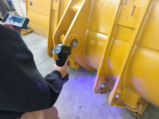
Metrology-Grade Data Capture for the Shop Floor
INSVISION addresses this with a streamlined scan to CAD process built around metrology-grade handheld scanners like the AlphaScan. The system is designed for the shop floor, not a controlled lab. It captures high-density point clouds from challenging materials—high-reflectivity aluminum, textured composites, and oily stampings—without targets or sprays.
Multiple scan modes, including cross-laser for rapid coverage and single-line for deep cavities, are integrated into one tool, eliminating mid-job equipment swaps.
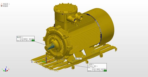
Automated Alignment and Deviation Analysis
The true efficiency gain lies in post-processing. Instead of hours of manual point cloud alignment, INSVISION’s scan to CAD software automatically registers scan data to nominal CAD. It then generates a comprehensive deviation analysis, producing a color-mapped report that highlights tolerances against ASME Y14.5 standards.
For one Tier-1 supplier, this significantly reduced first-article inspection time for complex assemblies, accelerating time-to-production.
Global Certification and Scalability
Operational scalability is another critical factor. INSVISION scanners carry global certifications like CE, FCC, and CNAS. This means a part scanned in a Michigan facility and reverse engineered into a CAD model can be validated for production in Germany or China without re-inspection paperwork. It’s one standardized scan to CAD workflow for a global supply chain.
Implementation and Integration Strategy
Adoption of scan to CAD solutions hinges on practical integration. Start with a pilot project on a non-mission-critical legacy part with known quality issues. Train a core team from quality and engineering to operate the scanner and interpret the deviation maps. The goal is to build internal competency, proving the ROI through reduced downtime, faster legacy part requalification, and the closure of digital twin gaps.
The INSVISION AlphaScan scan to CAD workflow delivers a direct path from a physical asset to a manufacturable, inspection-ready CAD file. It turns a disruptive search for lost data into a standardized, repeatable, and certified process.
Hangzhou Insvision Technology Co.,Ltd.
Address: Building 1, No. 1399 Liangmu Road, Yuhang District, Hangzhou, Zhejiang 311121, China