

Precision Under Pressure: Solving the Measurement Puzzle for Small Parts with 3D Scanning
Metrology teams working with miniature connectors, micro-molded components, and tiny medical implants face a persistent challenge: traditional touch probes and
The problem compounds when the part geometry combines tight radii, reflective surfaces, and features that sit below the surface plane. Small precision parts rarely present a single material type or a uniform finish. A single micro-molded connector housing can mix polished steel core pins, textured polymer bodies, and transparent seal surfaces.
Capturing the complete geometry in one setup, without coating or sectioning, requires a measurement approach that treats surface variability as a given rather than a disturbance.
Deployment Validation Checklist
| Focus Area | Decision Point | Deployment Note |
|---|---|---|
| Target part | Check size, surface condition, and key tolerances against the scan task | Run a full trial scan on a representative part |
| Data workflow | Verify point cloud, deviation map, and quality-report handoff | Confirm export formats and review ownership in advance |
| Shop-floor use | Review training, calibration, lighting, and working space | Keep the validation record as a repeatable inspection reference |
The Detection Pain Points That Conventional Tools Overlook
When a part’s largest dimension is under 20 mm, the inspection strategy cannot be a scaled-down version of a large-part workflow. Three factors converge to create measurement bottlenecks. The first is surface interaction. Highly reflective surfaces on polished pins, ground electrodes, or electroplated contacts saturate camera sensors, while dark or translucent polymers absorb projected light and return weak signals.
The second is feature density. Micro-connectors routinely pack 30 or more contact cavities into a 10 mm pitch, each with draft angles, parting line mismatches, and blind depth requirements. The third is structural fragility. Thin walls below 0.3 mm, fine cantilever snaps, and delicate spring fingers deform under the smallest contact force, making touch probing a risk to the very geometry being measured.
Key Points at a Glance
- When a part’s largest dimension is under 20 mm, the inspection strategy cannot be a scaled-down version of a large-part workflow.
- A productive workflow for small precision parts begins with object characterization, not equipment selection.
- Raw scan data on small parts is only as valuable as the alignment and analysis pipeline that follows.
- No single scanner configuration covers every small part scenario, but the decision criteria narrow quickly when the part family is defined.
Assembly context adds another layer of complexity. A small precision part is rarely inspected in isolation. Engineers need to verify mating interfaces, seal grooves, and snap-fit undercuts relative to a datum structure that may itself be only a few millimeters across.
Vision systems that rely on a single viewing angle cannot resolve occluded features, while CMMs with sub-millimeter ruby tips physically cannot reach into deep narrow slots. The result is a partial data set that leaves critical functional surfaces unchecked.
Building a Scanning Strategy Around the Part, Not the Scanner
A productive workflow for small precision parts begins with object characterization, not equipment selection. Technicians at INSVISION recommend mapping the part’s feature families before choosing a scan path. Metallic, glossy, dark, and transparent surfaces on the same component demand a scanner that adjusts exposure dynamically across the field of view.
The AlphaVista handheld blue-light structured-light scanner addresses this directly. Its narrowband blue light source cuts through ambient interference and generates clean fringe patterns on surfaces that typically confuse laser-based systems, while the multi-exposure capture sequence compiles data from dark and bright regions into a single cohesive point cloud without manual recalibration.
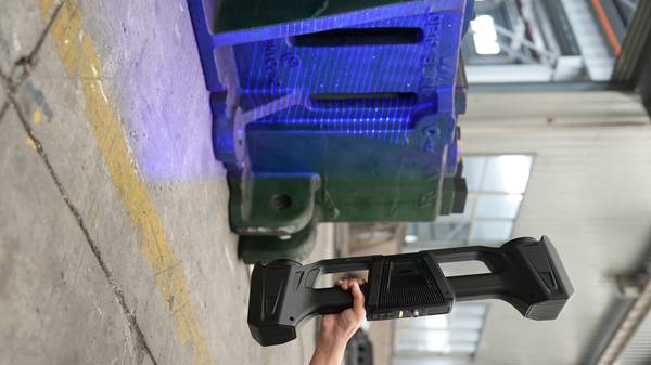
For parts with deep cavities, undercuts, or closely spaced pins, the handheld form factor becomes a practical advantage. A fixed scanner demands part rotation, fixturing, and multiple registration alignments. The AlphaScan handheld scanner lets the operator walk around the part, tilting the device to sight down into recessed features and capture sidewall geometry that a fixed mount would miss.
The software registers the accumulated frames in real time, flagging areas of low point density so the operator can fill gaps before leaving the workstation. This immediate feedback loop shortens the time between data capture and verification, particularly on parts that require first-article inspection reports with GD&T callouts on dozens of features.
From Point Cloud to Pass/Fail: The Data Closure Workflow
Raw scan data on small parts is only as valuable as the alignment and analysis pipeline that follows. The workflow generally moves through five steps: point cloud alignment to the CAD nominal, feature extraction and datum definition, surface comparison with color-mapped deviation, dimensional annotation of critical characteristics, and automated report generation.
On a part with a 10 mm overall length and a ±0.02 mm profile tolerance, the alignment quality alone determines whether the report is actionable or misleading.
The software environment matters here. INSVISION’s platform supports direct import of STEP and IGES models, pairs the scan data to the CAD reference through best-fit or datum-based alignment, and outputs a deviation map that highlights sink marks, warp, and short shots on molded parts or tool wear patterns on machined features.
A wall thickness analysis module can section the part at user-defined planes and display thickness values across the cross-section, a capability that proves especially useful for medical tubing and micro-fluidic channels where wall consistency directly impacts burst pressure.
The final report packages the GD&T results, deviation images, and statistical summaries into a PDF that can be archived alongside the batch record, closing the loop from shop floor measurement to quality documentation without manual transcription.
Selecting the Right Tool for the Small Parts Spectrum
No single scanner configuration covers every small part scenario, but the decision criteria narrow quickly when the part family is defined. The AlphaScan handheld scanner, with its lightweight build and multi-line laser mode, suits parts where the operator needs rapid surface acquisition and the flexibility to reposition the scanner continuously.
It is frequently chosen for reverse engineering of legacy small components, where no CAD model exists and the goal is to generate a watertight mesh for tooling design or CNC programming.
The AlphaVista scanner steps in when surface finish, color variation, and fine feature resolution take priority. Its structured-light engine captures high-density data on surgical staples, micro-optical housings, and electronic connector insulators where feature edges must be sharp and repeatable.
Both systems share the same software backbone, so a team that standardizes on INSVISION can move between the two devices without retraining or reformatting report templates. For manufacturers evaluating a small-part scanning investment, the practical starting point is a sample part review.
Submitting a representative component for a feasibility scan reveals which surfaces present problems and what level of deviation is achievable under real conditions, turning a technology decision into a process validation exercise rather than a specification comparison.
Hangzhou Insvision Technology Co.,Ltd.
Address: Building 1, No. 1399 Liangmu Road, Yuhang District, Hangzhou, Zhejiang 311121, China