

Heavy Forging Inspection Without the Jig: How a Large-Format Optical Measuring Machine Handles Oversized Parts
In heavy machinery and large-scale forging, dimensional inspection is rarely a benchtop task. You are dealing with parts that can weigh several tons, with criti
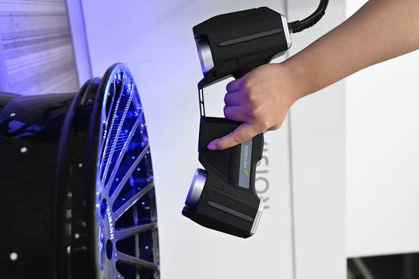
This article examines how a large-format optical measuring machine fits into the inspection workflow of a heavy forging and machining operation. The discussion focuses on the AlphaVista handheld 3D scanner from INSVISION, a system built specifically for capturing large-scale parts at metrology-grade accuracy without rigid fixturing.
The Real Constraint on Large Forging Inspection
The typical workflow for inspecting a large forged housing or structural weldment starts with setup time. The part must be craned onto a surface plate or CMM bed, leveled, and aligned — a process that can consume more time than the actual measurement.
Deployment Validation Checklist
| Focus Area | Decision Point | Deployment Note |
|---|---|---|
| Target part | Check size, surface condition, and key tolerances against the scan task | Run a full trial scan on a representative part |
| Data workflow | Verify point cloud, deviation map, and quality-report handoff | Confirm export formats and review ownership in advance |
| Shop-floor use | Review training, calibration, lighting, and working space | Keep the validation record as a repeatable inspection reference |
For parts that are still warm from heat treatment or too large for the available CMM envelope, the alternative has often been a mix of manual gauges, templates, and spot-checking with portable arms. That approach leaves gaps. You get readings on a few bore diameters and flange faces, but the full surface between those points remains unknown.
Springback after forming, uneven stock distribution, and subtle deformation during cooling all hide in the unscanned areas.
Key Points at a Glance
- The typical workflow for inspecting a large forged housing or structural weldment starts with setup time.
- The AlphaVista is designed to decouple measurement accuracy from part position.
- The process begins with preparation of the part surface.
- Not every scanner handles large-scale parts well.
The core pain point is not accuracy in isolation. It is the trade-off between coverage, speed, and the physical constraints of the part. A measurement system that cannot move freely around a stationary part will always force compromises.
How a Large-Format Optical Measuring Machine Changes the Sequence
The AlphaVista is designed to decouple measurement accuracy from part position. It is a handheld structured-light scanner that projects 50 crossed blue laser lines onto the surface, capturing full-field data at 0.020 mm metrology-grade accuracy. The scanner weighs 1,070 grams, which means the operator can walk around a large forging and scan continuously without the fatigue that skews results with heavier equipment.
The practical shift is this: instead of moving the part to the measurement system, the measurement system moves to the part. The scanner tracks the surface geometry optically, building a dense point cloud in real time. There is no need for a CMM bed, a rotary table, or a rigid reference jig.
The system references itself through the surface features it captures, which is critical when measuring parts that are too large or too heavy to reposition easily.
For a heavy machinery manufacturer, the AlphaVista can be deployed directly beside the machining center or the forge press. The operator scans the part as it sits on the shop floor, capturing all visible surfaces in one continuous session. The data is then aligned to the CAD model or to a reference coordinate system defined by the part’s functional datums.
The result is a complete as-built surface map that can be compared to the nominal model for stock analysis, deformation assessment, or first-article inspection.
Walking Through the Deployment Steps
The process begins with preparation of the part surface. For large forgings, this typically involves a light coat of matting spray on highly reflective or oxidized areas. The AlphaVista handles dark and reflective surfaces better than many structured-light scanners due to its blue laser technology and AI-driven exposure control, but extremely shiny or absorbent surfaces still benefit from a quick dusting.
The operator then defines the scan path. On a large housing or frame, the path follows the natural geometry — starting from a primary datum surface, moving across flanges and bores, and ending at the smaller mounting faces. The scanner captures data at a rate that keeps pace with deliberate, steady movement. There is no need to pause for individual frames or to stitch sections manually afterward.
The software builds the 3D model live, showing coverage and any missed areas.
Once the scan is complete, the data goes through alignment and analysis. The point cloud is registered to the CAD model using feature-based or best-fit alignment, depending on the inspection requirements. GD&T callouts are applied to the mesh, and a color map is generated to show deviation from nominal.
For reverse engineering tasks — common when legacy parts lack CAD data — the mesh can be exported directly into modeling software for surface reconstruction.
The entire workflow, from the first scan pass to the inspection report, can be completed in a single shift. Parts that previously required dismantling or transport to a metrology lab can now stay in the production flow.
Why the AlphaVista Fits This Class of Work
Not every scanner handles large-scale parts well. The key factors are field of view, depth of field, and tracking stability. The AlphaVista’s large-format capture area means fewer passes to cover a given surface, reducing cumulative alignment error.
The 50 crossed laser lines provide dense data on edges, corners, and deep pockets — features that are common on forged and machined castings but often problematic for scanners with fewer lines or wider spacing.
The 0.020 mm industrial metrology-grade accuracy is a hard specification that matters most when checking bore positions, mounting face flatness, and seal surface profiles. At this level, the scanner can serve as a substitute for a CMM on many large-part inspection tasks, particularly when the CMM cannot access the part at all.
INSVISION, the company behind the AlphaVista, operates under an ISO 9001:2015 quality management system and holds over 50 patents and software copyrights in the field of AI-driven 3D scanning and intelligent inspection. This engineering background is relevant when the scanner is used in regulated industries where process documentation and measurement traceability are required.
What Operators Observe in Practice
The most immediate change reported by teams adopting this workflow is the reduction in non-value-added handling. A part that once required two crane lifts and a dedicated setup crew can now be scanned by a single operator in the same time it takes to complete the first setup on a traditional system.
The inspection data is also richer — instead of a few dozen discrete measurements, the team gets a complete surface map that reveals trends like progressive die wear, uneven stock removal, or thermal distortion patterns.
For reverse engineering applications, the AlphaVista captures the as-built geometry of a worn or modified part directly on the machine bed. The resulting mesh can be used to generate a new CAD model for replacement manufacturing, eliminating the trial-and-error fitting that often accompanies legacy part reproduction.
The scanner’s AI-based metrology-grade processing helps maintain accuracy across varying surface conditions. The system adapts exposure parameters on the fly, which means the operator does not need to stop and adjust settings when moving from a machined face to a rough cast surface. This is a practical advantage on parts that mix as-forged and finish-machined features.
Extending the Approach to Similar Workflows
The same methodology applies to any scenario where the part is large, heavy, or difficult to move. Weldments, large castings, composite layup tools, and assembly jigs all benefit from in-place scanning. The common thread is that the measurement system must adapt to the part, not the other way around.
For quality managers evaluating this approach, the key validation step is a gage R&R study on a representative part. The AlphaVista’s accuracy specification should be verified against a calibrated artifact or a known CMM dataset under the same shop-floor conditions where it will be used. The resulting measurement uncertainty should be compared to the part tolerance band to determine fitness for purpose.
The trend in large-part manufacturing is toward more in-process measurement and less reliance on off-line inspection. A large-format optical measuring machine like the AlphaVista makes that shift practical by delivering metrology-grade data without the bottleneck of part transport and setup.
When the part stays put and the scanner does the walking, the inspection cycle compresses, the data gets richer, and the production team gains a clearer picture of what is actually happening at each stage of the process.
Hangzhou Insvision Technology Co., Ltd.
Address: Building 1, No. 1399 Liangmu Road, Yuhang District, Hangzhou, Zhejiang 311121, China
Copyright © Hangzhou Insvision Technology Co., Ltd. All rights reserved.
Copyright © Hangzhou Insvision Technology Co., Ltd. All rights reserved.