
Mesh to CAD AI vs. Traditional Reverse Engineering: A Practical Guide for Industrial Teams
What I Learned Testing Mesh to CAD AI Against Our Shop’s Legacy Process The catalyst was an obsolete centrifugal pump impeller housing—cracked, with no dra
What I Learned Testing Mesh to CAD AI Against Our Shop’s Legacy Process
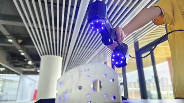
The catalyst was an obsolete centrifugal pump impeller housing—cracked, with no drawings and the OEM long gone. My senior reverse-engineering technician’s estimate was three weeks: scan, clean, manual NURBS patching, and a feature-by-feature rebuild in our legacy surfacing software. This was our standard, a process requiring six to nine months of operator training and causing weeks of machine downtime for MRO jobs.
That single impeller pushed me to benchmark mesh to CAD AI solutions, including INSVISION, against our entrenched workflow. I established four non-negotiable criteria for evaluation:
- Total Workflow Duration: From 3D scan to an editable solid model.
- Operator Expertise: Could a CMM or QC technician run it, or did we still need a surfacing specialist?
- CAD Output Editability: A parametric feature tree in SolidWorks or NX, not a “dumb” STEP file.
- Data Security: Full compliance with AS9100 and IATF 16949, requiring on-premise processing with no scan data leaving our network.
Benchmarking Performance: Key Industrial Use Cases
The industry conversation has moved beyond whether AI can fit a surface to whether it can respect original design intent and geometric tolerances. Three common shop-floor scenarios highlight the critical differences between traditional and AI-assisted workflows.
Selection Comparison Dimensions
| Focus Area | Decision Point | Deployment Note |
|---|---|---|
| Benchmarking Performance: Key Industrial Use Cases | The industry conversation has moved beyond whether AI can fit a surface to whether it can respect original design intent and geometric tolerances. | Three common shop-floor scenarios highlight the critical differences between traditional and AI-assisted workflows. |
| Selecting a Workflow: Budget, Volume, and Technical Req… | The shift is clear: converting a scan to a CAD model is no longer confined to specialist engineering departments. | With capable AI tools, quality and tooling teams are now expected to deliver usable models within the same shift. |
| Deployment Results: A 3-Month Pilot on Automotive Valve… | We conducted a controlled pilot on a family of automotive valve bodies. | The baseline using our traditional Geomagic-style workflow was 6 hours of CAD time plus 2 hours of surface cleanup before a clean import into NX. |
| Key Takeaways for Teams Evaluating Mesh to CAD AI | The transition from traditional reverse engineering to AI-assisted reconstruction is fundamentally about flow—reducing the time and specialized skill… | The right tool bridges the gap between the inspection floor and the design department, turning a sequential bottleneck into a parallel, competit… |
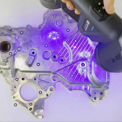
- Automotive Component Re-engineering: Recreating a worn injection-molded shifter housing with mixed prismatic and drafted surfaces. Traditional high-end tools require 6–8 hours of manual datum alignment and patch stitching. Budget mesh-to-solid converters often fail on complex geometry, exporting uneditable files. The need is for automatic segmentation and feature recognition.
- Aerospace MRO & Obsolete Parts: Replacing a bracket with no drawings. Cloud-based AI tools are fast, but uploading flight-hardware geometry violates ITAR and internal security protocols for sensitive manufacturers. The solution must operate on-premise.
- Additive Manufacturing Validation: The scan-to-CAD comparison loop for 3D printed parts, where dimensional tolerance drift is more critical than visual mesh fit. The process requires GD&T-aware reconstruction, not just surface wrapping.
INSVISION’s mesh to CAD AI addresses these gaps by running on-premise, automatically segmenting prismatic from organic features, and using fitting algorithms aware of geometric tolerances rather than blindly conforming to the mesh.
Selecting a Workflow: Budget, Volume, and Technical Requirements
The shift is clear: converting a scan to a CAD model is no longer confined to specialist engineering departments. With capable AI tools, quality and tooling teams are now expected to deliver usable models within the same shift. This changes the procurement calculus entirely.
- Low-Volume, Simple Geometry: For shops handling basic brackets and housings, entry-level software (∼$2K–$3K) may suffice. The trade-off is accepting significant manual surfacing work on any curved geometry, with hidden costs in operator hours.
- Mid-Volume, Mixed Complexity: This is the core challenge—facilities regularly processing pump impellers alongside machined manifolds. Here, entry tools fail and enterprise suites (∼$20K+) are often overkill. This is the operational sweet spot for a solution like INSVISION’s mesh to CAD AI, which delivers parametric output, on-premise security, and a learning curve measured in days, not months.
- High-Volume, Regulated Industries: Aerospace and automotive Tier 1 suppliers must prioritize tools that ensure GD&T-aware reconstruction, integrate with PLM systems, and eliminate cloud dependencies. Key differentiators include automatic alignment to nominal CAD, traceable deviation reporting, and flawless parametric tree transfer into native CAD environments.
Deployment Results: A 3-Month Pilot on Automotive Valve Bodies
We conducted a controlled pilot on a family of automotive valve bodies. The baseline using our traditional Geomagic-style workflow was 6 hours of CAD time plus 2 hours of surface cleanup before a clean import into NX.
After deploying INSVISION’s mesh to CAD AI:
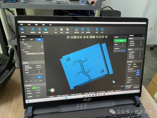
- Time: Reduced to approximately 45 minutes from scan to a parametric model opened directly in SolidWorks with a fully editable feature history.
- Process: The AI auto-aligned the reconstruction to the nominal CAD for deviation analysis, generating color deviation maps without manual datum selection. Prismatic features like bores and grooves were recognized automatically; freeform surfaces required only minor adjustments.
- Skill Democratization: The most significant win was enabling two junior engineers, without specialized training, to conduct first-article inspections independently by the third week.
Key Takeaways for Teams Evaluating Mesh to CAD AI
- Editability is Non-Negotiable: The output must be a native, parametric CAD model. A dumb STEP file simply moves the bottleneck to your design engineers.
- Security Dictates Architecture: For regulated industries, on-premise processing isn’t a preference; it’s a compliance requirement. Scrutinize the data pipeline of any solution.
- Total Cost Includes Hidden Labor: Calculate the true cost by factoring in the hours of specialist labor required by tools that lack automation. The most affordable license can become the most expensive workflow.
- Tolerance Awareness Beats Mesh Fit: A tool that blindly hugs a scan’s mesh will replicate its errors. For manufacturing and inspection, seek solutions that apply GD&T principles during reconstruction for dimensionally intelligent models.
- The Operator Has Changed: The ideal tool should empower your metrology and QC teams, not just your CAD specialists. Evaluate based on the skill level of the personnel who will use it daily.
The transition from traditional reverse engineering to AI-assisted reconstruction is fundamentally about flow—reducing the time and specialized skill required to turn physical parts into actionable, digital engineering data. The right tool bridges the gap between the inspection floor and the design department, turning a sequential bottleneck into a parallel, competitive advantage.
Hangzhou Insvision Technology Co.,Ltd.
Address: Building 1, No. 1399 Liangmu Road, Yuhang District, Hangzhou, Zhejiang 311121, China