
How to Evaluate metrology tools for optical manufacturing for Industrial
In heavy manufacturing, three inspection patterns dominate, and each carries a built-in compromise.
Typical Workflows and Their Breaking Points
In heavy manufacturing, three inspection patterns dominate, and each carries a built-in compromise. Fixed CMMs provide traceable accuracy but create a logistical bottleneck: parts queue for the machine, and any deviation discovered hours after machining has already propagated into additional workpieces.
Wired optical trackers improve portability but tether the operator to a workstation cart, complicating scans inside confined turbine housings or around assembly jigs where cables snag on tooling. Manual checks with calipers, micrometers, and flush-pin gauges are fast and shop-floor friendly, but they sample only discrete points, missing form deviations that span between measured locations.
The common thread is that inspection remains a batched, off-line activity. Data arrives too late to correct a drifting process in real time, and the overhead of part handling, fixturing, and requalification inflates the true cost of quality.
For large parts that cannot be moved—an assembled fuselage section, a wind turbine blade root on a service platform—the only practical option has been to bring the measurement tool to the asset. Until recently, that meant sacrificing either accuracy or data density.
A Different Measurement Architecture
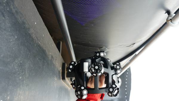
The INSVISION X-Track replaces single-beam tracking with a multi-sensor dynamic triangulation approach. A 520 nm visible laser (Class 3R, <5 mW, eye-safe for shop-floor use) is tracked in real time by multiple optical sensors, solving for six degrees of freedom as the operator moves the handheld probe around the part.
This architecture maintains a coordinate lock at 0.25 mm volumetric positioning accuracy even when the probe briefly passes behind a fixture or the operator walks to the far side of a large assembly—exactly the line-of-sight interruptions that cause single-beam systems to drop data and require re-referencing.
The measurement chain aligns to ISO 10360 geodetic and coordinate measuring system standards, so dimensional data flows directly into existing quality workflows without translation steps. More importantly, the system’s optical tracking calibration actively compensates for ambient light variation. Shop floors mix overhead LEDs, sunlight through bay doors, and shadowed corners;
the X-Track holds its accuracy specification across these conditions without a controlled lab environment. For optical manufacturing and large-tooling metrology, that environmental robustness is what separates a practical production tool from a delicate lab instrument.
How the System Lands on the Shop Floor
Deployment follows a sequence familiar to any quality team integrating new optical measurement equipment. At a Tier-1 automotive stamping plant, a quality engineer positions the X-Track unit beside a large body-side panel.
Pre-deployment calibration aligns the system’s coordinate frame to the part datum structure per ASME Y14.5 GD&T callouts, with a certified length artifact verifying volumetric accuracy for ISO 17025 traceability before any production data is collected. Setup takes under 30 minutes—rolling cart for the shop floor, flight case for field MRO.
The operator then runs a first-article scan, capturing the full surface geometry. To validate repeatability, the same reference features are re-measured across five consecutive runs, confirming consistency within the system’s 0.020 mm accuracy band. If drift exceeds tolerance, a quick re-reference restores alignment without a full recalibration cycle.
Training follows a role-based split: operators learn scan paths and fixture setup, while quality engineers focus on GD&T evaluation and reporting. For facilities with specialized requirements—custom laser power for dark composite surfaces, integration with proprietary automation—INSVISION handles OEM and ODM modifications at the design stage, not as retrofits.
Where the X-Track Fits the Application
The system’s design choices map directly to the pain points described earlier. At 9.5 kg, the unit is light enough for a quality team to carry between work cells without rigging. The all-metal chassis and sealed optics survive the knocks of daily use in heavy manufacturing.
Native USB 3.0 and Ethernet ports push dense point-cloud data to analysis software at line speed, so a 3D scan of a large casting does not become a data-transfer bottleneck.
On the software side, direct export to IGES, STP, DXF, and DWG means measurement data flows straight into existing CAD/CAM and quality management platforms without intermediate file conversions—a detail that avoids the hidden cost of reformatting scripts and keeps the digital thread intact from scan to statistical process control dashboard.
The operating temperature range of -5°C to 40°C covers everything from unheated receiving docks to sun-baked assembly yards, eliminating the recalibration anxiety that typically accompanies moving optical metrology tools between indoor and outdoor environments.
CE, FCC, and CNAS certifications give Western engineering and EHS managers documented proof of compliance with international safety and electromagnetic compatibility standards, streamlining site approvals.
Observable Operational Shifts
Teams that deploy the X-Track report a consistent pattern of change, even if the specifics vary by industry. In aerospace MRO, technicians map large structural components directly on the hangar floor, capturing surface deviation and edge geometry without lifting the part onto a CMM.
Automotive OEM body-in-white teams run dynamic scene scanning on moving assembly lines, checking GD&T callouts in real time and flagging drift before it produces scrap. On-shore wind energy service crews scan blade root sections and hub mating surfaces in situ, where contact probing would risk laminate damage and take hours longer.
For large medical device mold reverse engineering, the system digitizes complex cavity geometries without the stylus pressure that can deform polished tooling surfaces.
Across these scenarios, the common shift is from delayed batch inspection to in-process verification. The system streams live scan data to a workstation while the operator moves, enabling quality decisions that keep production flowing. Fewer parts sit in quarantine. Measurement workflows adapt to the part, not the other way around.
| Operational Strength | Application Scenario |
|---|---|
| Wireless optical tracking with 0.25 mm positioning accuracy | Large-volume aerospace component inspection requiring GD&T validation on the assembly jig |
| Real-time industrial metrology data output | In-process automotive assembly line quality checks aligned with lean manufacturing targets |
| Broad operating temperature range and 9.5 kg portable form factor | Field-based energy turbine MRO and legacy part reverse engineering |
| Native support for standard CAD formats and PLM system integration | Cross-team quality validation and digital thread alignment for Industry 4.0 facilities |
Extending the Approach to Similar Environments
The underlying principle—bringing metrology-grade optical measurement equipment to the asset rather than moving the asset to the metrology lab—applies wherever large, high-value, or difficult-to-transport components require dimensional verification.
Heavy fabrication shops inspecting welded structures, railcar maintenance depots assessing frame geometry, shipbuilding yards checking hull subassemblies, and defense contractors validating ground-support equipment all face the same logistical calculus. The key evaluation criteria remain consistent: Can the system hold its accuracy specification in the actual lighting and temperature conditions of the workspace?
Does it integrate with existing CAD and quality platforms without manual data translation? Can a single operator set up and scan without assistance? The X-Track’s architecture addresses these questions directly, making it a reference point for teams moving inspection from the lab to the line.
Summary
The INSVISION X-Track represents a practical evolution in large-volume metrology, not because it introduces a single breakthrough technology, but because it resolves the real-world conflicts between accuracy, portability, and environmental tolerance that have historically forced manufacturers to choose between speed and data quality.
For procurement and engineering groups assessing metrology tools for optical manufacturing optical measurement equipment, the operational distinction is straightforward: this system shifts inspection from a batched, lab-dependent activity to a continuous, on-site process, reducing the hidden costs of part movement, production stoppages, and rework that accumulate when measurement data lags behind manufacturing reality.
Hangzhou Insvision Technology Co.,Ltd.
Address: Building 1, No. 1399 Liangmu Road, Yuhang District, Hangzhou, Zhejiang 311121, China