

From Part Geometry to Inspection Reports: 3D inspection of reflective industrial par
Industrial quality teams have long accepted a frustrating trade-off: the parts most worth measuring are often the hardest to scan. Polished bearing journals, ch
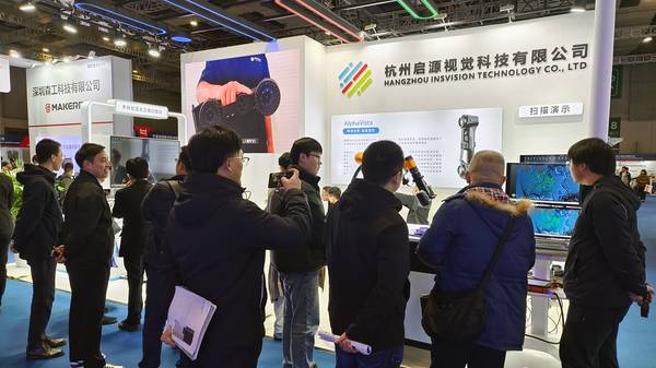
The AlphaScan handheld 3D scanner from INSVISION was designed with this problem class in mind. Rather than treating reflectivity as an edge case, the system addresses it as a core measurement condition.
Blue laser scanning combined with multi-exposure imaging allows the device to capture data across a wide dynamic range, reading dark and bright zones in a single pass without requiring operators to coat parts with developer spray. This matters because spraying adds time, introduces thickness uncertainty, and is often forbidden on cleanroom components or parts that will be returned to service.
Deployment Validation Checklist
| Focus Area | Decision Point | Deployment Note |
|---|---|---|
| Target part | Check size, surface condition, and key tolerances against the scan task | Run a full trial scan on a representative part |
| Data workflow | Verify point cloud, deviation map, and quality-report handoff | Confirm export formats and review ownership in advance |
| Shop-floor use | Review training, calibration, lighting, and working space | Keep the validation record as a repeatable inspection reference |
When a part is inherently reflective — a mirror-finished aerospace valve seat, a polished injection mold core, or a precision-ground gear flank — the inspection workflow must adapt to the surface, not the other way around.
Part Characteristics That Define the Inspection Problem
Reflective industrial parts share a few physical traits that make optical measurement difficult. The first is specular reflection: light hitting a polished surface bounces directionally rather than scattering, so the sensor receives either a blinding spike or nothing at all. Second is curvature.
A cylindrical bearing journal or a spherical ball stud reflects light differently across its surface, creating zones that are overexposed near the center of curvature and too dark at the edges. Third is material heterogeneity. Parts that combine polished metal with matte coatings, black anodized surfaces, or textured gaskets force the scanner to resolve radically different albedos in the same frame.
Scenario Snapshot
A practical way to read the article is through this scenario:
- Part Characteristics That Define the Inspection Pro…: Reflective industrial parts share a few physical traits that make optical measurement difficult.
- Building a Scan Strategy Around the Object: A successful scan of a reflective part begins not with the scanner but with the object itself.
- From Point Cloud to Actionable Inspection Data: Once the scan is complete, the data pipeline determines whether the effort translates into a quality decision or j…
Geometry adds another layer of difficulty. Deep bores, narrow oil galleries, and intersecting cross-holes are common in fluid control components, hydraulic valve bodies, and fuel system parts. A scanner must capture the inner walls of a 6 mm bore while also holding accuracy on the adjacent flat sealing face.
The AlphaScan addresses this with a compact scan head and short standoff distance, allowing the operator to angle the device into confined spaces. Where a fixed CMM probe might require multiple stylus changes and fixture reorientations, the handheld scanner can collect bore depth, diameter, and thread profile data in a continuous scanning motion.
Surface condition further complicates the picture. A freshly machined part may have a directional lay from grinding or turning, creating micro-grooves that polarize reflected light. The same part after plating or polishing behaves differently. INSVISION’s software includes algorithms that analyze the intensity histogram of each frame and adjust exposure parameters frame by frame, reducing the need for manual recalibration.
This is particularly useful in production environments where operators move between part families with different finishes within the same shift.
Building a Scan Strategy Around the Object
A successful scan of a reflective part begins not with the scanner but with the object itself. The operator needs to understand where the critical-to-quality features are located, which surfaces are datum references, and what tolerances apply. For a typical precision component — say, a chrome-plated hydraulic piston rod — the critical features include the outer diameter, the flatness of the end face, and the chamfer geometry.
The rod is cylindrical, specular, and prone to creating highlights along its length. Without a clear strategy, the scanner will capture the edges well but leave an axial stripe of missing data.
The approach begins with part orientation. Setting the rod on a stable fixture with the axis slightly tilted relative to the scan plane helps distribute reflections more evenly. The operator makes a quick pass to establish the global coordinate system, then concentrates on feature-rich zones.
The AlphaScan’s real-time preview shows point cloud density, so the operator can see immediately whether a region needs a second pass from a different angle. This instant feedback replaces the old workflow of scanning blind, processing the data, finding gaps, and returning to the part.
For parts with mixed surfaces — a black anodized bracket bolted to a polished stainless steel flange — the multi-exposure capability becomes essential. The scanner captures the same area with different exposure settings, and the software merges the data into a single coherent mesh. This eliminates the need to spray the dark area or mask the bright area.
The process is fast enough that a complete scan of a fist-sized assembly can be completed in under two minutes, including the time needed to reposition the part once.
From Point Cloud to Actionable Inspection Data
Once the scan is complete, the data pipeline determines whether the effort translates into a quality decision or just a pretty 3D model. The raw point cloud is processed to remove outliers, align with the nominal CAD model, and generate a color map that shows deviation at every point on the surface.
For a reflective gear carrier, this map might reveal that the bearing bore is 15 microns undersized on one side, a condition that would be difficult to detect with a dial bore gauge but becomes immediately visible on the deviation map.
The CAD comparison step is where metrology fundamentals take over. The operator selects datum features according to the engineering drawing, performs a best-fit or RPS alignment, and applies the defined tolerance zones. The software then produces a report that lists each measured feature, its nominal value, actual value, deviation, and pass/fail status.
For parts that require statistical process control, the measured values can be exported to a CSV file for trending analysis. INSVISION’s platform supports export to common inspection report formats, so the data can flow into existing quality management systems without manual transcription.
A practical workflow includes a repeatability check. After the initial scan, the operator removes the part from the fixture, repositions it, and scans again. Comparing the two datasets reveals whether the fixture strategy is stable and whether the scanner is returning consistent results.
On a ground steel shaft with a diameter tolerance of ±12 microns, the agreement between repeat scans should be well within the measurement uncertainty budget. This kind of verification is standard practice for metrology-grade scanning and should be part of any inspection protocol for reflective parts.
What to Look for When Selecting a 3D Scanner for Reflective Surfaces
The scanner specification sheet tells only part of the story. A device may list high accuracy under ideal conditions but degrade significantly on polished metal. When evaluating a system for reflective parts, the first thing to check is how it handles dynamic range. Can it capture a part that has both a mirror-like surface and a matte black coating in the same scan, without spray and without operator intervention?
The second is software capability. Automated mesh cleanup, intelligent hole filling that respects curvature, and robust CAD alignment algorithms make the difference between a finished report in 10 minutes and an hour of manual editing.
Portability and environmental tolerance also matter. Many reflective parts are large or permanently installed — machine tool spindles, turbine shafts, die-casting molds. A scanner that can be carried to the part eliminates the need to disassemble and transport heavy components.
The AlphaScan operates on battery power and connects to a tablet or laptop, so scans can be performed on the shop floor, in the tool room, or at incoming inspection.
INSVISION’s certifications including CE, FCC, and ISO 9001 quality management system registration provide a baseline for equipment reliability, though buyers should always verify that the specific performance claims match their part geometry and tolerance requirements.
The final consideration is the learning curve. A scanner that requires a dedicated metrology programmer to operate will not be used as frequently as one that a quality technician can pick up after a day of training. The software interface should guide the operator through alignment, scanning, and reporting without exposing every advanced parameter at once.
As the team gains experience, they can explore deeper features like custom coordinate systems, batch processing, and integration with SPC software. The goal is a system that becomes part of the daily inspection rhythm, not a specialized tool that sits in a cabinet waiting for the annual audit.
For manufacturers dealing with polished, plated, or ground surfaces, matching the scanner to the material reality of the parts is the foundation of a reliable digital inspection process.
Hangzhou Insvision Technology Co.,Ltd.
Address: Building 1, No. 1399 Liangmu Road, Yuhang District, Hangzhou, Zhejiang 311121, China