

3D Scanning Malaysia Deployment Guardrails for In-House Quality Teams
3d scanning malaysia: Common 3D Scanning Adoption Gaps in Malaysian Manufacturing Facilities Common 3D Scanning Adoption Gaps in Malaysian Manufacturing.
Common 3D Scanning Adoption Gaps in Malaysian Manufacturing Facilities
Most Malaysian export-oriented factories do not fail at buying a 3D scanner. They fail at the point where the scanner has to sit inside an existing quality system and produce evidence an auditor will accept. The gap between a clean demo scan and a live production inspection is where implementation stalls.
A handheld scanner that looks fast in a supplier showroom may still leave a quality engineer manually aligning point clouds for hours when the workpiece is a stamped automotive bracket with 200 holes. The equipment is rarely the problem. The deployment logic usually is.
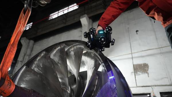
Deployment Validation Checklist
| Focus Area | Decision Point | Deployment Note |
|---|---|---|
| Target part | Check size, surface condition, and key tolerances against the scan task | Run a full trial scan on a representative part |
| Data workflow | Verify point cloud, deviation map, and quality-report handoff | Confirm export formats and review ownership in advance |
| Shop-floor use | Review training, calibration, lighting, and working space | Keep the validation record as a repeatable inspection reference |
Scenario Snapshot
A practical way to read the article is through this scenario:
- Common 3D Scanning Adoption Gaps in Malaysian…: Most Malaysian export-oriented factories do not fail at buying a 3D scanner.
- Pre-Deployment Sample Validation Protocols for…: As automotive chassis assemblies grow larger and more structurally integrated, quality teams face a difficult…
- On-Site V-Track Integration Without Disrupting…: In many Malaysian Tier 1 and Tier 2 manufacturing plants, the conversation around dimensional inspection has…
Overreliance on spec sheet comparisons without workflow testing is one of the most common traps. Procurement teams in Malaysia serving automotive, aerospace, and electronics OEMs often shortlist scanners by scanning area, laser line count, and nominal accuracy.
Those numbers matter, but they do not tell you how long it takes to scan a deep hole with a single blue laser line, or what happens when an operator moves from precision scanning with seven blue laser lines to high-speed scanning on a large cast housing. A spec sheet comparison also misses whether the software export format matches what the CMM programmer already uses.
The result is a scanner that meets every line item on the purchase requisition but does not fit the inspection routing.
The second gap is misalignment with existing IATF 16949 or AS9100 inspection protocols. Malaysian facilities that already pass these audits have documented control plans, first-article inspection reports, and gage R&R studies. Dropping a new 3D scanning system into that environment without defining how scan data becomes a controlled inspection record creates a parallel process.
Quality engineers end up running the CMM for the official report and the scanner for troubleshooting. That duplication is not a technology failure. It is a failure to map scan outputs to the existing PPAP, FAI, or in-process verification workflow before deployment.
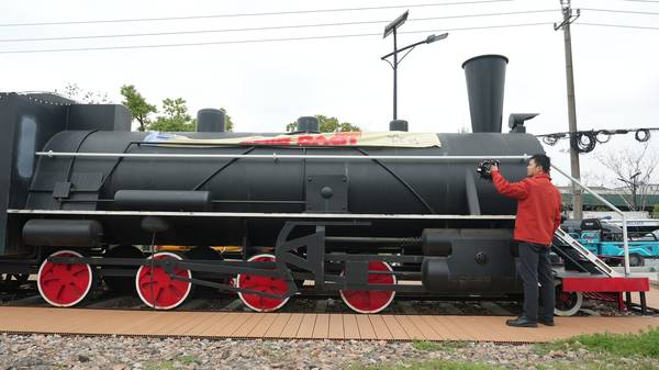
Underplanning for large workpiece tracking is the third recurring issue. Export-oriented work increasingly involves bigger assemblies, longer weldments, and full-surface inspection of parts that cannot be moved easily. A scanner that performs well on a benchtop fixture may struggle when the operator has to walk around a large aerospace component while maintaining coordinate reference.
Without a tracking strategy, scan alignment drifts, and the operator spends more time stitching than measuring. INSVISION addresses this with the V-Track tracking 3D scanning system, which is designed around the need to keep large workpieces referenced during scanning without relying on dozens of target stickers or rigid fixturing.
These gaps are not warnings to avoid investing in 3D scanning in Malaysia. They are signals that structured pre-deployment validation belongs in the purchasing process. A factory that scans its own worst-case workpiece, on its own shop floor, against its own inspection protocol before committing to a system will almost always avoid the failures that show up three months after installation.
The rest of this guide outlines what that validation should look like.
Pre-Deployment Sample Validation Protocols for Production Fit
As automotive chassis assemblies grow larger and more structurally integrated, quality teams face a difficult shift. The old habit of checking a few critical holes with a CMM and assuming the rest of the stamping is stable no longer holds. Welded subframes, hydroformed rails, and cast suspension nodes now carry complex, interacting tolerances across a metre or more of sheet metal.
When a new measurement system is proposed for these parts, the real question is not whether the scanner works on a calibration block. It is whether the system will hold up against the variation already present in production — the springback, the weld distortion, the slight differences from one die set to the next.
INSVISION addresses this before any equipment reaches the customer’s floor through a pre-deployment sample validation protocol. The goal is simple: prove production fit on representative workpieces, using the customer’s own quality criteria, before on-site delivery.
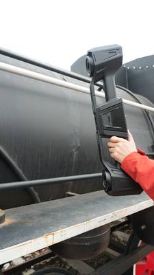
For a representative Malaysian automotive component manufacturer producing large chassis assemblies, the validation process starts with sample selection. The customer’s quality team, together with INSVISION application engineers, picks test workpieces that are not master parts.
They deliberately include assemblies with known issues: a rail with deep draw features, a crossmember with stacked weld flanges, a bracket cluster with tight hole patterns. These parts reflect real production spread, not ideal CAD. The intention is to test the V-Track tracking 3D scanning system against the same geometric variation the line produces on a daily basis.
Deep features and occluded areas are left in place, because those are exactly the regions where a CMM probe struggles and where a scanning system must demonstrate clear value.
During validation, the V-Track system scans each selected workpiece using tracking-based data acquisition. The resulting point cloud is aligned to the part’s CAD model, and key characteristics are extracted: hole positions, slot widths, surface profiles, flange angles, and edge trim conditions. These measurements are then cross-referenced with the factory’s existing CMM spot-check data.
The comparison is not limited to a single alignment or a best-fit overview. Individual features are evaluated against the same GD&T callouts the plant already uses for first-article inspection and in-process audits. Where CMM data exists for a given hole or surface point, the V-Track result is placed side by side with it. The pass/fail criteria are not invented by INSVISION.
They are taken directly from the manufacturer’s current quality standards and drawing requirements. If a hole position must hold within a given tolerance band, the validation report uses that exact band. If a surface profile has a form tolerance, the scan data is analysed to the same zone. This alignment with existing standards is what makes the step meaningful.
The customer is not being asked to accept a new measurement philosophy; they are seeing whether the scanning system can reproduce and extend the inspection logic they already trust.
The practical outcome of this pre-deployment step is a documented fit confirmation. The manufacturer sees, on their own parts and against their own tolerances, how the V-Track system behaves. Any concerns about scanning deep pockets, handling shiny or oiled surfaces, or holding alignment across a large assembly are addressed before the system is packed and shipped.
This eliminates the common post-purchase surprise where a scanner arrives, gets installed, and only then reveals a mismatch with the plant’s actual inspection needs. For Western buyers evaluating 3D scanning Malaysia projects, this protocol matters because it shifts the discussion from brochure specifications to production evidence. The system is not sold on theoretical accuracy.
It is validated on the parts that will actually run through the line. That is the difference between buying a measurement device and integrating a production-ready inspection tool.
On-Site V-Track Integration Without Disrupting Production Takt
In many Malaysian Tier 1 and Tier 2 manufacturing plants, the conversation around dimensional inspection has shifted noticeably over the last two years. Quality teams that once relied almost exclusively on fixed CMMs and hard gauges are now being asked to validate larger castings, welded fabrications, and composite layups without pulling parts offline for hours.
The pressure comes from two directions: downstream customers are tightening GD&T callouts on first-article submissions, while production planners are less willing to surrender floor space or takt time for measurement. In this environment, the question is no longer whether optical metrology can work in a production cell, but whether it can be installed without forcing a line reconfiguration.
The INSVISION V-Track deployment process is built around that constraint.
A common scenario is a quality inspection cell located at the end of a machining or welding line. The cell already has a designated staging area, a reference table, and a workflow where an inspector receives parts, checks critical dimensions, and releases them to the next operation. The V-Track system is positioned to work within that existing layout rather than replace it.
During the initial site walk, the INSVISION application team maps the available floor space, identifies the inspector’s movement path, and confirms the maximum workpiece envelope. The optical tracker is typically mounted on a mobile or semi-fixed stand that can be moved aside when the cell is needed for other tasks.
Because the tracker does not require a dedicated metrology room or a thermally controlled enclosure, it can sit directly adjacent to the staging area. The scan head remains handheld, which means the inspector does not have to manipulate a heavy fixture or crane the part onto a granite table for every measurement.
Large workpieces that require repositioning mid-scan are a central concern in these deployments. A welded frame or a machined housing often exceeds the visible tracking volume from a single orientation. To handle this, the V-Track system uses tracking reference points placed on the workpiece or on a stable fixture.
When the inspector rotates the part or moves to scan a hidden face, the tracker continuously references those points to maintain coordinate alignment. The reference configuration is planned during installation so that the points remain visible across the expected range of motion.
For parts that are flipped or rolled, the team establishes a repeatable repositioning sequence, often using simple V-blocks, risers, or existing shop-floor supports. The goal is not to eliminate repositioning, but to make it predictable and fast enough that the inspector does not lose registration between scan passes. This approach avoids the need for a turntable or a dedicated scanning booth in most cases.
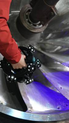
Installation scheduling is handled around production constraints. The INSVISION team typically requests access during planned shift breaks, tool changeovers, or preventive maintenance windows. The initial setup includes mounting the tracker, calibrating the system against a certified reference artifact, and running a short validation scan on a known workpiece.
This can often be completed within a single break window, with fine-tuning done during the first live inspection cycle. The software setup is equally important. INSVISION configures the inspection template, imports the nominal CAD model, and defines the measurement features that the quality team needs to report.
Existing quality workflows are preserved: the inspector still follows the same release procedure, but the dimensional data is now captured optically and exported in the format the plant already uses, whether that is a CSV report, a PDF snapshot, or a deviation color map.
For the inspection team, the practical benefit is that the V-Track system becomes another tool in the cell, not an isolated station. Parts that previously waited for CMM availability can be scanned at the staging area and released based on immediate deviation feedback. For large parts with multiple critical features, the tracking reference points allow the inspector to work around the workpiece in a natural sequence.
The system does not force a full line overhaul or require the plant to carve out a dedicated scanning room. That is the core deployment logic: fit the metrology to the existing process, not the other way around.
Data Output Compatibility With Existing Quality Management Systems
The verification step is where most 3D scanning deployments in Malaysia either succeed or quietly fail. A scanner can capture excellent geometry, but if the exported data does not drop cleanly into the quality team’s existing software and reporting workflow, the equipment ends up as an isolated measurement island.
Quality managers end up exporting files manually, re-entering dimensions into spreadsheets, and maintaining two versions of inspection truth. That is exactly what the data output verification process is designed to prevent.
For V-Track deployments, INSVISION treats data compatibility as a formal acceptance criterion, not an afterthought. Before a system is handed over to production, the integration team runs a structured verification sequence against the factory’s current metrology stack. This typically starts with the point cloud and mesh export formats.
The team confirms that V-Track scan data imports cleanly into the CAD comparison tools already licensed and in daily use at the site. Common formats include standard mesh and point cloud outputs that mainstream inspection software can read without third-party conversion utilities. If the factory uses a particular build of comparison software, the verification includes that exact version, not a generic equivalent.
The next layer is inspection report formatting. Export-focused Malaysian manufacturers often operate under audit requirements tied to aerospace primes, medical device customers, or automotive OEMs. These audits expect traceability: part number, serial or batch identifier, operator ID, date and time stamp, scan parameters, and revision-controlled report templates.
The verification process maps V-Track report fields to those existing QMS requirements. If the factory’s current first-article inspection report has a specific header structure or GD&T callout layout, the exported report is configured to match it. This matters more than it sounds. A quality engineer should not need to copy deviation values from one PDF into another template by hand.
That manual step is where transcription errors enter, and it is also where audit findings originate.
Automated report templates are configured during the same verification phase. The goal is to reduce manual data entry for quality teams, not to add another reporting task to their day. For example, a dimensional inspection routine that previously required an operator to type measured values into a spreadsheet can instead pull those values directly from the scan session.
The template is set up once, validated against a known reference part, and then locked for routine use. Subsequent scans populate the report fields automatically. This removes a significant source of variation in the data chain.
The verification also checks that scan data feeds into existing reporting workflows rather than creating a parallel silo. In practical terms, this means the quality manager can open the same folder structure, the same report viewer, and the same audit trail they used before the scanner arrived. The only change is that measurement data now originates from a 3D scan instead of a CMM or hand tool.
That continuity is what allows a 3D scanning Malaysia deployment to become part of the quality system instead of a disconnected measurement project that fades after the initial pilot.
For factories evaluating a V-Track system, this verification step should be written into the acceptance criteria from the start. Ask the integration team to demonstrate a complete data flow: scan a reference part, export the point cloud, import it into the existing comparison software, generate a report, and confirm the report matches the current QMS format.
If any step requires a workaround, resolve it before production rollout. The verification process exists to catch those gaps early, when they are still configuration issues rather than daily workflow disruptions.
In-House Team Training and Post-Launch Review Cycles
A 3D scanning system only earns its place on the shop floor when the quality team actually uses it. That sounds obvious, but plenty of factories have learned the hard way that a capable scanner sitting idle is just expensive furniture. INSVISION treats deployment as a training and workflow problem, not a hardware handoff.
For Malaysian factory quality teams, that means a structured program built around the parts they inspect every day, the software they will open every shift, and the small operational questions that tend to surface in the first few weeks.
The training starts with role-specific sessions. Quality engineers and inspectors do not sit through the same generic slides. Instead, INSVISION runs hands-on practice using production workpieces from the customer’s own lines. This is important because scanning a clean calibration block in a training room is not the same as scanning a stamped bracket with oil residue, edge burrs, or reflective surfaces.
Operators learn how to position parts, manage scan angles, and decide when to switch scanning modes based on geometry. For example, a part with deep pockets or narrow slots may require the single blue laser line mode for deep hole scanning rather than a multi-line precision mode. The goal is not just button familiarity. The team needs to build judgment about what a good scan looks like and what needs a second pass.
Data processing guidance is just as structured. Many quality teams already have some metrology background, but the jump from touch probing or hand gauges to point-cloud processing is not automatic. INSVISION adapts the pace to the team’s existing knowledge level. A team comfortable with CMM reporting may move quickly through alignment and GD&T callouts.
A team coming from manual inspection may need more time on mesh cleanup, reference alignment, and export formats. Either way, the training follows the same sequence: scan, align, extract features, compare to CAD or drawing requirements, and generate a report the production team can act on.
Basic troubleshooting is part of the initial training, not an afterthought. Operators learn what to do when scan data looks noisy, when alignment fails, or when a reflective surface is not capturing cleanly. These are common operational questions, and the point is to keep the system running without waiting for remote support.
Simple fixes, like adjusting exposure, cleaning the part surface, or repositioning the scanner, are covered in the context of the customer’s own workpieces.
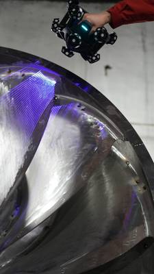
After launch, INSVISION schedules 30-day and 90-day review sessions. The 30-day check usually focuses on early pain points. Maybe one shift is struggling with a particular part family. Maybe a fixture is blocking access to a critical surface. Maybe the report template needs adjustment to match the factory’s existing quality documentation. These sessions are working meetings, not surveys.
The INSVISION team watches the operators scan real parts, identifies where the process slows down, and adjusts the workflow accordingly.
The 90-day review goes deeper. By then, the team has enough experience to see where scanning fits into high-volume production, not just first-article inspection. Workflows get refined for repeatability across shifts. For example, a common adjustment is standardizing part setup so that the night shift gets the same scan quality as the day shift. Another is fine-tuning the balance between scan density and processing time.
High-volume parts do not need excessive point-cloud density if the inspection callouts are stable. The review helps the team settle into a rhythm that delivers consistent value without overprocessing.
Across both review cycles, the measurable outcome is not just scan accuracy. It is adoption. The system becomes part of the quality loop rather than a special project. INSVISION’s approach works because it respects the team’s existing metrology knowledge, builds on it, and removes the early friction that causes new equipment to be quietly set aside.
When the 90-day session ends, the factory is not left with a scanner and a manual. It is left with a working inspection process that multiple shifts can run independently.
Replicating This Deployment Framework Across Malaysian Industries
The V-Track framework transfers most directly to facilities where workpieces are large, repositionable, or difficult to move to a fixed CMM. Aerospace MRO operations in Selangor fit this pattern well. Airframe components, nacelle panels, and repaired structural sections often sit on stands or fixtures that make traditional inspection awkward.
A tracking-based system lets quality teams scan in place, build deviation maps against CAD, and feed results into existing AS9100-aligned documentation without re-rigging the part. The same logic applies to consumer electronics enclosure manufacturers in Penang, where first-article inspection on molded or machined housings benefits from fast surface capture and hole identification.
Johor heavy equipment component plants represent another strong fit. Large castings, weldments, and wear surfaces can be scanned in the service bay or at the line, then compared to nominal geometry before machining or after rework.
Three qualifying factors matter more than industry classification. First, the workpiece must be physically accessible and stable enough for tracking. Parts that vibrate, flex, or sit in congested cells create avoidable error. Second, the facility should already operate some form of ISO-aligned quality workflow. V-Track does not replace a quality system; it plugs into one.
Teams that understand inspection planning, datum control, and report traceability will extract far more value than teams starting from zero. Third, the organization should want to build internal 3D scanning capacity.
Facilities that currently outsource dimensional inspection or rely on third-party layout services are often the best candidates, provided they have an in-house quality team ready to own the equipment, the software workflow, and the data deliverable.
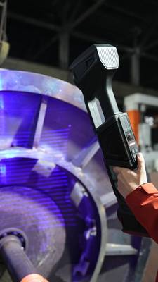
A quick assessment checklist helps separate realistic deployments from forced fits. Ask whether the typical workpiece exceeds the practical range of a fixed CMM or requires disassembly before inspection. Ask whether the team already works from CAD models or can obtain them.
Ask whether inspection reports need to follow ISO or ASME conventions, and whether the current process produces enough repeat measurements to justify internal capacity. Ask whether operators can dedicate time to scanning, post-processing, and report generation rather than treating the system as a side task.
If most answers point toward large, accessible parts, existing quality discipline, and internal ownership, the V-Track approach is likely replicable. If not, a benchtop scanner or a different inspection strategy may be more appropriate.
Hangzhou Insvision Technology Co., Ltd.
Address: Building 1, No. 1399 Liangmu Road, Yuhang District, Hangzhou, Zhejiang 311121, China
Copyright © Hangzhou Insvision Technology Co., Ltd. All rights reserved.
Copyright © Hangzhou Insvision Technology Co., Ltd. All rights reserved.