

What to Validate Before a 3D Measurement System Reaches the Production Floor
3d measurement system: A 3D measurement system can look convincing in a controlled demonstration and still stall on the first day of production.
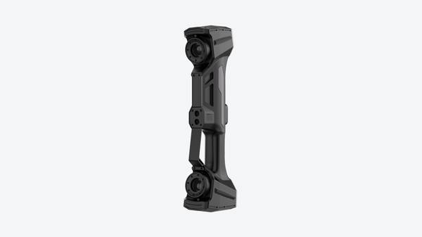
These are not equipment faults. They are unvalidated assumptions about part size, surface behavior, access, light, and data deliverables. This guide explains how to evaluate a 3D measurement system against real production conditions before it becomes a bottleneck.
What a 3D Measurement System Does and Where Its Limits Begin
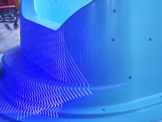
A 3D measurement system converts physical geometry into digital coordinates. Most industrial optical systems project structured light or a laser pattern onto a part, record how the pattern deforms across the surface, and reconstruct a point cloud. That point cloud can then be turned into a mesh, compared with CAD nominals, or used to generate dimensional reports tied to geometric dimensioning and tolerancing.
Key Points at a Glance
- A 3D measurement system converts physical geometry into digital coordinates.
- A robust validation checks more than scan repeatability on a demo block.
- Handheld optical measurement fills a different role than a fixed coordinate measuring machine or an articulated arm.
- Large-format optical measurement is well suited to large sheet metal assemblies, castings, large fabrications, reverse engineering of legacy par…
Accuracy is not a single number. It depends on sensor calibration, tracking stability, surface response, part access, and the quality of the reference alignment. Because the process is optical and line-of-sight, conditions that do not appear on a datasheet can change the result. A glossy surface may saturate the sensor. A dark textured surface may not return enough signal.
A large assembly may require the scanner to move around the part while maintaining stable tracking. If the part cannot be moved, the 3D measurement system must go to the part.
Key Technical Elements to Validate on Production Parts
A robust validation checks more than scan repeatability on a demo block. It tests whether the system can handle the actual parts, light, access, and reporting requirements on the floor.
| Validation factor | What to check with real parts | Common failure if skipped |
|---|---|---|
| Part geometry and size | Full scan cover age, tracking across deep pockets, thin edges, large freeform surfaces | Incomplete coverage or hidden features |
| Surface finish | Exposure on polished, dark, oiled, or textured surfaces | Sparse point clouds or overexposed regions |
| Required outputs | Mesh, deviation map, GD&T report, PMI alignment, native CAD export | Manual rework or unusable inspection records |
| Access and lighting | Fixture clearance, dark zones, glare areas, path around large parts | Line-of-sight loss or poor scan quality |
| Data workflow | Import into CAD, PLM, QMS, report format, audit trail | Bottlenecks discovered after go-live |
The most useful validation uses a representative set of production parts rather than vendor demonstration pieces. Demo blocks show sensor repeatability under controlled conditions, but they do not prove that a system can capture full freeform surfaces, inner flanges, or the exact finish condition on the line.
Production samples should include the largest part, the smallest critical feature, the shiniest surface, and the least accessible area.
Where Handheld Optical Measurement Differs from Fixed and Contact Systems
Handheld optical measurement fills a different role than a fixed coordinate measuring machine or an articulated arm. A fixed CMM provides tight single-point accuracy when the part can be brought into a controlled environment. An arm-based system offers flexible contact or noncontact probing within a limited reach radius.
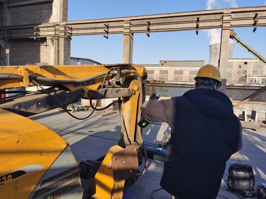
A handheld optical 3D scanner captures full-field surface data quickly and can travel to the part, but it depends on line-of-sight, surface contrast, and stable handling.
| Workflow | Typical strength | Main boundary condition | Application fit |
|---|---|---|---|
| Fixed CMM | Tight single-point accuracy, established GD&T routines | Part must be moved to the machine; controlled environment | Small-to-medium machined parts |
| Arm-based scanning | Contact and noncontact flexibility | Reach radius and transport constraints | Fixtures, localized surfaces |
| Handheld optical 3D scanner | Full-field surface data, mobility, large part coverage | Needs line-of-sight, markers or texture, consistent handling | Large fabrications, castings, MRO, legacy parts |
The distinction is not better or worse. It is fit for the inspection task. A 3D measurement system that works well for large freeform surfaces may not be the right first choice for a tight single-point tolerance inside a deep bore.
Where a 3D Measurement System Fits—and Where It Should Not Be the First Choice
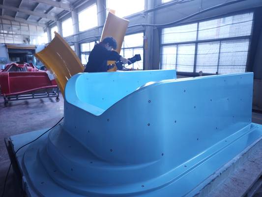
Large-format optical measurement is well suited to large sheet metal assemblies, castings, large fabrications, reverse engineering of legacy parts, as-built documentation for MRO, and first-article inspection where full-surface comparison matters. The main value is mobility and full-field coverage.
The limitations are also clear. Optical measurement is less suitable when the tolerance requires tactile single-point verification in a deep internal cavity, when surfaces are mirror-polished or transparent and cannot be prepared, when micro-scale internal features require non-optical inspection, or when severe vibration prevents stable tracking.
Deployment Validation: Aligning the 3D Measurement System with Quality Workflows
Successful adoption starts by mapping where inspection data enters existing quality gates. In lean manufacturing and Industry 4.0 environments, quality teams should walk each production line or MRO bay and identify current checkpoints, data owners, GD&T callouts, and downstream record systems. The 3D measurement system should plug into those gates rather than create a parallel process.
Data output compatibility matters as much as scan accuracy in aerospace, medical device, and energy applications. Before full rollout, confirm that the system can export native CAD formats for Catia, NX, SolidWorks, or Creo instead of forcing STEP or IGES conversion later.
Check whether inspection reports can be generated in standardized formats such as PDF with embedded CSV or QIF/MBD data aligned to AS9102, PPAP, or ISO 13485 documentation requirements. If these interfaces are not verified during validation, engineering teams often discover the bottlenecks only after the scanner is already on the shop floor.
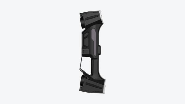
INSVISION AlphaVista in Large-Format Handheld Measurement Workflows
INSVISION positions AlphaVista for the large-format handheld scanning segment. For production teams evaluating mobile measurement, the key test is whether the system travels to the part, keeps tracking across large surfaces, and produces the required outputs under real shop-floor lighting.
The engineering benefit is workflow fit. A large-format handheld scanner reduces the need to stage large parts or dismantle fixtures for measurement. INSVISION supports AlphaVista deployments with role-specific training so engineers focus on tolerance interpretation, alignment methods, and GD&T callouts, while technicians build repeatable scanning routines, part positioning skills, and scanner care habits.
That separation helps avoid the common situation where every operator understands only one narrow measurement routine.
Long-term use is where large-format handheld systems add practical value. An AlphaVista unit can move from incoming supplier inspection on castings to reverse engineering of legacy aerospace parts or as-built capture for MRO records.
Portability and a broad measurement range make cross-site application realistic, but teams should verify repeatability after relocation and retrain users on new part geometry or reporting requirements.
Common Misconceptions and Technical Q&A
Does a 3D measurement system replace a CMM?
Not automatically. In most plants it complements a CMM. A handheld optical system captures full-field surface data and travels to large or difficult-to-move parts. A CMM still provides tight single-point control in a controlled environment. The right choice depends on whether full-surface coverage or specific point tolerances drive the inspection.
Why not rely on vendor demonstration parts?
Demonstration blocks prove sensor repeatability under controlled conditions. They do not replicate fixture access, ambient light, part size, surface oil, or the exact GD&T outputs required on the line. Use actual production parts or a representative sample set.
What if the scanner outputs mesh data but not inspection reports?
For first-article inspection, a mesh alone may not be enough. Verify that the system can compare scan data to CAD nominals and generate GD&T reports in formats that match AS9102, PPAP, or ISO 13485 documentation needs. Native CAD and QMS integration should be confirmed before full rollout.
Can one handheld system serve multiple production lines or MRO sites?
Yes. Large-format handheld systems such as INSVISION AlphaVista are designed for mobility. However, teams should verify repeatability after relocation, confirm lighting and access conditions, and retrain users on any new part geometry or reporting requirements.
The Practical Takeaway
A 3D measurement system succeeds through validation, not through specification alone. Production parts, real lighting, actual access constraints, and clean data handoffs are the tests that matter. Teams that build these checks into the selection process are more likely to end up with a measurement workflow that fits the production floor, supports quality documentation, and remains useful as inspection needs change.
Hangzhou Insvision Technology Co., Ltd.
Address: Building 1, No. 1399 Liangmu Road, Yuhang District, Hangzhou, Zhejiang 311121, China
Copyright © Hangzhou Insvision Technology Co., Ltd. All rights reserved.
Copyright © Hangzhou Insvision Technology Co., Ltd. All rights reserved.