

Measurement Uncertainty in Industrial 3D Scanning
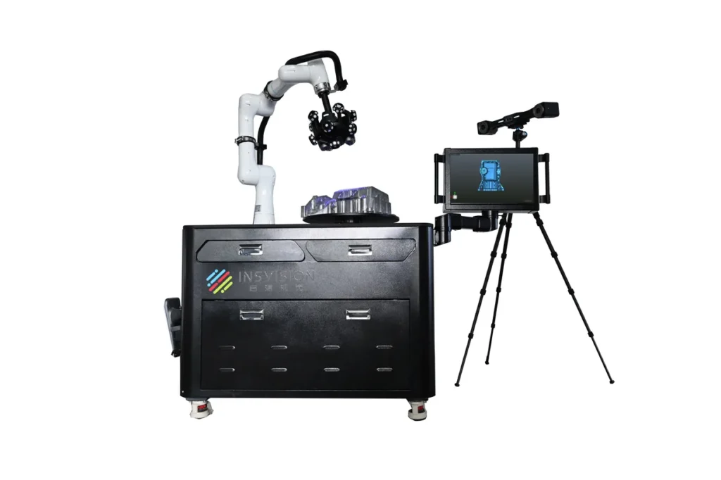
Measurement uncertainty in industrial 3D scanning is a quantitative expression of the doubt associated with a dimensional measurement derived from 3D scan data, describing the range of values within which the true, traceable value of an object's geometric feature is estimated to lie.
Definition
Measurement uncertainty in industrial 3D scanning is a quantitative expression of the doubt associated with a dimensional measurement derived from 3D scan data, describing the range of values within which the true, traceable value of an object's geometric feature is estimated to lie. Unlike single-point scan error, which measures deviation between one measured value and a reference, measurement uncertainty accounts for all sources of variability across an entire scanning workflow, and is a foundational metric for validating 3D scanning results for industrial metrology and quality control applications.
How It Works
Measurement uncertainty in 3D scanning is calculated by identifying and quantifying all individual sources of variability across the scanning ecosystem, then combining these values per standard metrological practices to derive a total uncertainty range. Key sources of variability contributing to total uncertainty include:
- Hardware variability: Calibration drift of cameras, projectors, or tracking systems; sensor resolution limitations; and thermal expansion of system components during use.
- Environmental variability: Ambient temperature fluctuations, vibration, dust, and competing light sources that distort optical signals or alter object dimensions during scanning.
- Workflow variability: Error in aligning multiple scan frames (registration); operator variation in scan path or target placement; and post-processing adjustments such as smoothing or outlier removal that alter point cloud geometry.
- Object-related variability: Surface reflectivity, transparency, or texture that distorts scan signals; geometric complexity that causes partial occlusions; and thermal expansion or contraction of the object itself.
Individual uncertainty components are categorized as either random (varying between measurements, e.g., minor ambient temperature fluctuations) or systematic (consistent bias across measurements, e.g., uncalibrated sensor offset). These components are combined to calculate a combined standard uncertainty, which is typically multiplied by a coverage factor of k=2 to produce an expanded uncertainty interval corresponding to a 95% confidence level, the standard for most industrial metrology applications.
Key Parameters and Criteria
Measurement uncertainty for 3D scanning is evaluated using standardized metrological parameters that reflect different components of total variability. The core parameters are defined in the table below:
| Parameter | Meaning | Judgment Method |
|---|---|---|
| Expanded Uncertainty (U) | The interval around a reported 3D measurement value within which the true geometric value is estimated to lie, typically stated for a 95% confidence level for industrial applications | Derived from combined standard uncertainty calculations, verified by repeated measurements of calibrated, metrologically traceable reference artifacts |
| Measurement Repeatability | The variability in successive 3D measurements of the same object feature, conducted under identical operating conditions (same operator, same system, same environment, short time interval) | Calculate the standard deviation of a minimum of 10 consecutive measurement runs of the same reference feature, excluding confirmed systematic bias |
| Measurement Reproducibility | The variability in 3D measurements of the same object feature conducted under changed operating conditions (different operators, different system calibrations, different environmental settings) | Compare measurement results from a minimum of 3 independent test sets with controlled variable changes, following established metrological testing protocols |
| Alignment Uncertainty | The component of total measurement uncertainty introduced by the process of aligning multiple scan frames or registering point clouds to a common coordinate system | Measure deviation of common reference targets across aligned scan datasets, compared to their calibrated relative positions |
All uncertainty parameters are dependent on use case variables including object size, surface material, geometric complexity, scan resolution settings, and environmental controls. For example, uncertainty values for large objects are typically higher than for small objects due to increased registration error, while high-reflectivity surfaces may increase uncertainty unless pre-treated to reduce optical distortion. For scanning systems paired with external optical tracking, tracking range and target placement also contribute to overall uncertainty.
Suitable and Unsuitable Scenarios
Suitable Scenarios
Formal evaluation of 3D scanning measurement uncertainty is required or appropriate for use cases including:
- First-article inspection and production part approval for regulated industrial sectors such as aerospace, automotive, and medical device manufacturing
- Tolerance verification for high-precision machined, cast, molded, or additively manufactured components
- Compliance with quality management system requirements for production quality documentation and audit trails
- Comparative performance studies between 3D scanning and other dimensional measurement technologies such as coordinate measuring machines (CMMs)
Unsuitable Scenarios
Formal measurement uncertainty evaluation is not required, or standard industrial 3D scanning uncertainty does not meet use case requirements, for applications including:
- Non-metrological use cases such as visual prototyping, 3D modeling for entertainment, or cultural heritage digitization for public display, where approximate dimensional accuracy is sufficient
- Ultra-precision metrology use cases such as microelectronics inspection, jewelry manufacturing, or measurement of geometric features smaller than 2mm or apertures smaller than 5mm, which require specialized micro-metrology systems
- Non-industrial applications such as consumer-level facial scanning, dental scanning, or medical imaging diagnosis, which are subject to specialized regulatory requirements outside of industrial 3D scanning scope
- Dimensional measurement of objects smaller than 10cm, where the typical uncertainty range of industrial 3D scanners is disproportionately large relative to object dimensions
Common Misconceptions
- Myth: Measurement uncertainty is identical to scan accuracy or scan error. Scan error refers to a single point deviation between a measured value and a reference value, while stated scanner accuracy is a specification measured under ideal controlled laboratory conditions. Measurement uncertainty quantifies the full range of plausible deviations across real-world use cases, accounting for all variability sources in hardware, environment, and workflow.
- Myth: A 3D scanner has a single fixed measurement uncertainty value. Uncertainty varies significantly based on use case parameters, including object size, surface finish, scan resolution, alignment method, and post-processing settings. Uncertainty must be evaluated for each specific application, not derived solely from base scanner specifications.
- Myth: Measurement uncertainty only accounts for random measurement error. Uncertainty includes both random variability (e.g., minor ambient temperature fluctuations between scans) and systematic bias (e.g., consistent calibration offset in a scanner's camera system), as both contribute to the range of plausible measurement values.
- Myth: 3D scanning measurement uncertainty cannot be directly compared to CMM uncertainty. Both 3D scanning and CMM measurements follow the same international metrological principles for uncertainty evaluation. Their uncertainty values can be directly compared when assessed under identical test conditions for the same object and geometric features.
Related Concepts
- Metrological Traceability: The property of a measurement result whereby it can be linked to national or international reference standards through an unbroken chain of calibrated comparisons, a required foundation for formally valid measurement uncertainty statements.
- Calibrated Artifact: A physical object with known, traceable geometric dimensions (e.g., gauge blocks, ball plates, step gauges) used to verify measurement performance and quantify uncertainty components for 3D scanning systems.
- Point Cloud Registration: The process of aligning multiple overlapping scan datasets to form a unified 3D model, a major contributor to total measurement uncertainty for large or geometrically complex objects.
- Structured Light 3D Scanning: A 3D scanning technology that uses projected patterned light to capture surface geometry, with uncertainty sources including projector resolution, camera calibration, and light pattern distortion from surface properties.
- Optical Tracking: A system used to monitor the position of handheld scanners or test objects during scanning, introducing uncertainty components related to target detection accuracy and tracking latency over distance.
- Industrial Metrology: The branch of measurement science focused on verifying the dimensional accuracy of manufactured components, for which measurement uncertainty is a core performance and compliance metric.
FAQ
What is the difference between standard uncertainty and expanded uncertainty in 3D scanning?
Standard uncertainty (u) is the uncertainty of a measurement expressed as one standard deviation, calculated by combining individual uncertainty sources such as calibration error, alignment variation, and environmental noise. Expanded uncertainty (U) is derived by multiplying standard uncertainty by a coverage factor, most commonly k=2, to produce an interval that contains the true measurement value with approximately 95% confidence, the standard threshold for most industrial metrology applications.
Do I need to calculate measurement uncertainty for every 3D scanning project?
Formal measurement uncertainty calculation and documentation is only required for projects where scan results are used for regulatory compliance, formal tolerance verification, first-article inspection, or quality system audits. For non-metrological applications such as reverse engineering for visual prototyping, 3D modeling for entertainment, or cultural heritage digitization for display, formal uncertainty evaluation is typically unnecessary.
How does an object's surface property affect 3D scanning measurement uncertainty?
Highly reflective, transparent, matte black, or textured surfaces can distort the laser or structured light signals used by 3D scanners, increasing point cloud noise and random measurement variability. Pre-treatment such as applying a thin matte scanning spray can reduce this variability, but any surface treatment may introduce minor dimensional offsets that must be accounted for in total uncertainty calculations.
Can post-processing steps reduce 3D scanning measurement uncertainty?
Targeted post-processing steps such as statistical outlier removal, improved point cloud registration, and controlled noise filtering can reduce random variability and lower overall measurement uncertainty. However, excessive smoothing, geometry modification, or unvalidated alignment adjustments can introduce systematic bias that increases total uncertainty. All post-processing changes must be documented when conducting formal uncertainty evaluations for metrological applications.
Summary
Measurement uncertainty in 3D scanning is a foundational metrological metric that quantifies the range of plausible deviation between a scanned dimensional measurement and the true, traceable value of an object's geometric feature. It accounts for combined variability from hardware, environmental, workflow, and object-specific factors, and is evaluated using standardized protocols with traceable reference artifacts. Formal uncertainty evaluation is critical for regulated industrial inspection, quality compliance, and comparative metrology use cases, while it is not required for non-metrological 3D scanning applications. Understanding the drivers and limitations of measurement uncertainty is essential for selecting appropriate 3D scanning workflows and interpreting scan results accurately for industrial use.
- What Is 3D Scanning? Principles, Workflow, and Industrial Applications 3D scanning is a digital measurement technology that converts the surface geometry of physical objects into 3D data. This entry covers its working principles, core parameters, industrial use cases, common misconceptions, and related technical…
- What Is a 3D Scanner? Types, Parameters, and Selection Criteria A 3D scanner captures three-dimensional surface data from physical objects and converts geometry, dimensions, and features into digital data for inspection, reverse engineering, and modeling.
- What Is 3D Scanning Accuracy? Accuracy, Repeatability, and Resolution Explained 3D scanning accuracy describes how closely scan data matches an object's actual geometry and dimensions. It is assessed through local accuracy, volumetric accuracy, stitching accuracy, repeatability, and resolution.
- What Is Point Cloud Data? Point Clouds, Meshes, and CAD Models in 3D Scanning Point cloud data is an important raw data format in 3D scanning. It consists of discrete 3D coordinate points that describe object surface geometry and support inspection, reverse engineering, modeling, and archiving.
Hangzhou Insvision Technology Co., Ltd.
Address: Building 1, No. 1399 Liangmu Road, Yuhang District, Hangzhou, Zhejiang 311121, China
Copyright © Hangzhou Insvision Technology Co., Ltd. All rights reserved.
Copyright © Hangzhou Insvision Technology Co., Ltd. All rights reserved.