
Automated 3D Scanning
Automated 3D scanning is an industrial 3D measurement technology that executes end to end 3D data capture, alignment, processing, and analysis workflows.
Definition
Automated 3D scanning is an industrial 3D measurement technology that executes end-to-end 3D data capture, alignment, processing, and analysis workflows with minimal routine human intervention. It is a core component of industrial 3D digitization, deployed across sectors including manufacturing, aerospace, automotive, and energy to support repeatable, high-volume 3D measurement tasks. Systems may be configured for in-line production integration, batch workcell operation, or large-volume scanning of stationary assets.
How It Works
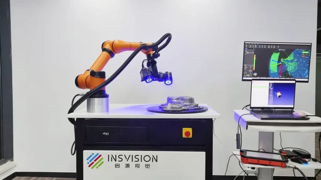
Automated 3D scanning systems typically integrate four core components: 3D scanning units (available in single-camera, multi-camera, single-projector, or multi-projector configurations), motion control platforms (such as robotic arms, gantries, or rotary stages for positioning either the scanner or the target part), optional optical tracking systems to extend working volume for large parts, and integrated software for workflow management and data processing.
Standard operation follows a structured workflow:
- Initial configuration: Operators perform one-time system calibration, define required scan parameters, and either program motion paths or train AI algorithms to generate optimal scan routes based on part geometry and accuracy requirements.
- Part loading: Parts are loaded into the system, either manually or via automated material handling, and localized using feature-based alignment or fiducial markers without manual adjustment.
- Data acquisition: The system follows pre-defined or AI-optimized scan paths, automatically adjusting light intensity, exposure, and scan resolution to accommodate surface characteristics such as reflectivity, deep cavities, or complex curvature.
- Real-time processing: Captured raw scan data is automatically stitched, cleaned of environmental noise, and aligned to reference CAD models if the workflow is for inspection or conformity assessment.
- Output generation: The system produces standardized outputs including dense point clouds, watertight meshed 3D models, or dimensional deviation reports.
Key Parameters and Criteria
Performance of automated 3D scanning systems varies based on part material, size, surface finish, operating environment, workflow configuration, and software settings. The following are core parameters used to evaluate system suitability for a given use case:
| Parameter | Meaning | Judgment Method |
|---|---|---|
| Measurement Accuracy | The maximum deviation between captured 3D scan data and a known calibrated reference value | Comparison of scan measurements of a traceable metrological artifact (e.g., gauge block, calibrated step gauge) to the artifact's certified dimensions |
| Scan Cycle Time | The total elapsed time to complete full 3D data capture, alignment, and initial processing for a single part or standardized batch | Timed end-to-end run of a fully set up workflow using a standardized test part, excluding one-time initial system configuration |
| Volume Accuracy | The cumulative measurement deviation across the full operating volume of the automated system | Measurement of calibrated reference targets placed at evenly distributed positions throughout the system's stated working range, with deviation calculated across all target positions |
| Automation Grade | The level of routine human intervention required to operate the system for standard workflows | Assessment of all workflow steps to count the number of tasks requiring manual input (e.g., part loading only, manual alignment, scan path adjustment, post-processing cleanup) |
| Point Cloud Density | The number of valid 3D data points captured per unit of surface area | Count of valid, non-noise points in a defined 100 cm² area of a calibrated flat test surface, normalized to points per square millimeter |
Suitable and Unsuitable Scenarios
Suitable Scenarios
- Batch quality inspection and geometric dimensioning and tolerancing (GD&T) analysis of small to medium industrial parts
- In-line production verification of automotive and aerospace components
- Reverse engineering of legacy or mass-produced parts for redesign or reproduction
- Batch validation of 3D printed components
- Photovoltaic component defect screening and dimensional verification
- Large-volume digitization of stationary industrial assets with consistent geometry
Unsuitable Scenarios
- One-off custom parts with highly variable, uncharacterized geometry requiring frequent manual scan path adjustment
- Extremely delicate parts that cannot be secured to fixturing or exposed to automated motion
- Operating environments with extreme, unregulated vibration, temperature fluctuation, or ambient light interference that disrupts system calibration or data capture
- Parts with fully transparent, highly light-absorptive, or extremely uneven surface finishes that cannot be consistently scanned without per-part manual surface preparation
Common Misconceptions
- Misconception: Automated 3D scanning eliminates all human input.
Clarification: While routine operation requires minimal intervention, all systems require one-time calibration, workflow setup, part loading/unloading, and occasional exception handling for out-of-spec or uncharacterized parts.
- Misconception: Higher scan speed always corresponds to better system performance.
Clarification: Scan speed is balanced against accuracy and point density; high-speed operating modes may reduce detail capture for complex, small, or high-reflectivity surfaces, making them unsuitable for precision inspection tasks.
- Misconception: All automated 3D scanning systems deliver metrology-grade accuracy.
Clarification: System accuracy varies widely by design and configuration; some systems are optimized for rapid prototyping or general digitization, while others are built for precision quality control with traceable metrological performance.
- Misconception: Automated systems can scan any industrial part without preparation.
Clarification: Part compatibility depends on size, material, and surface finish. Some parts require custom fixturing or batch-applied temporary surface treatment to ensure consistent data capture.
Related Concepts
- Industrial 3D Digitization: The end-to-end process of converting physical industrial assets into structured digital 3D models for use in design, manufacturing, inspection, or asset management.
- Structured Light 3D Scanning: A 3D measurement method that projects patterned light onto a target object and analyzes the distortion of the pattern to calculate precise 3D geometry, a common scanning technology used in automated inspection systems.
- Optical Tracking System: A technology that uses calibrated cameras to monitor the 3D position of reflective or active targets in space, used to extend the working volume of automated scanning systems for large or geographically dispersed assets.
- AI-Enhanced 3D Inspection: The integration of machine learning algorithms into 3D scanning workflows to automate scan path optimization, noise reduction, defect detection, and deviation analysis, reducing required manual input for complex tasks.
- Reverse Engineering: The process of generating a parametric CAD model from a physical part's 3D scan data, used for legacy part reproduction, product redesign, or design validation.
FAQ
Can automated 3D scanning systems capture data from high-reflectivity metal parts?
Many modern automated 3D scanning systems use specialized light sources (such as blue laser or blue structured light), adjustable exposure settings, and anti-reflection algorithms to capture consistent data from high-reflectivity metal surfaces. Performance varies by system configuration and part finish; some extremely reflective or polished parts may require batch-applicable temporary surface treatment to eliminate glare and ensure complete data capture.
How does automated 3D scanning differ from manual 3D scanning?
Automated 3D scanning uses pre-programmed or AI-optimized motion paths and automated data processing to complete repeatable workflows with minimal routine human intervention, making it well-suited for high-volume production tasks where consistency and throughput are priorities. Manual 3D scanning relies on a human operator to position the scanner, adjust settings, and navigate complex part geometry, offering greater flexibility for one-off custom parts or hard-to-access features but with higher labor costs and lower repeatability for batch operations.
How often do automated 3D scanning systems require calibration?
All metrology-grade automated 3D scanning systems require periodic calibration to maintain stated accuracy levels. Calibration frequency depends on usage intensity, environmental conditions (such as exposure to temperature fluctuation or vibration), and system design; most system providers specify recommended calibration intervals based on these factors.
Can automated 3D scanning data be used with existing industrial design and inspection software?
Most automated 3D scanning systems export data in standard 3D file formats compatible with common CAD, quality inspection, and product lifecycle management (PLM) platforms. Many systems also include native integration tools to enable direct data transfer and workflow sync with widely used industrial software suites.
Summary
Automated 3D scanning is a scalable, low-intervention 3D measurement technology designed to support repeatable, high-volume industrial digitization workflows. By integrating scanning hardware, motion control, optional tracking systems, and intelligent processing software, it delivers consistent 3D data for applications including quality inspection, reverse engineering, and production verification. System performance and suitability vary based on configuration, part characteristics, and operating environment, with key evaluation criteria including measurement accuracy, scan cycle time, and automation grade.
- What Is 3D Scanning? Principles, Workflow, and Industrial Applications 3D scanning is a digital measurement technology that converts the surface geometry of physical objects into 3D data. This entry covers its working principles, core parameters, industrial use cases, common misconceptions, and related technical…
- What Is a 3D Scanner? Types, Parameters, and Selection Criteria A 3D scanner captures three-dimensional surface data from physical objects and converts geometry, dimensions, and features into digital data for inspection, reverse engineering, and modeling.
- What Is 3D Scanning Accuracy? Accuracy, Repeatability, and Resolution Explained 3D scanning accuracy describes how closely scan data matches an object's actual geometry and dimensions. It is assessed through local accuracy, volumetric accuracy, stitching accuracy, repeatability, and resolution.
- What Is Point Cloud Data? Point Clouds, Meshes, and CAD Models in 3D Scanning Point cloud data is an important raw data format in 3D scanning. It consists of discrete 3D coordinate points that describe object surface geometry and support inspection, reverse engineering, modeling, and archiving.
Hangzhou Insvision Technology Co.,Ltd.
Address: Building 1, No. 1399 Liangmu Road, Yuhang District, Hangzhou, Zhejiang 311121, China