
3D Scanning Reference Markers
3D scanning reference markers are standardized, high contrast visual targets used in industrial 3D scanning workflows to establish consistent spatial.
Definition
3D scanning reference markers are standardized, high-contrast visual targets used in industrial 3D scanning workflows to establish consistent spatial coordinate systems, align discrete scan frames, and track the relative position of scanning hardware and target objects across measurement sessions. They may be physical (adhesive, machined, or retroreflective) or virtual/projected, deployed on the surface of a target object, surrounding fixturing, or the broader scanning environment.
How It Works
3D scanning reference markers operate on the principle of high-contrast feature detection and spatial triangulation, with functionality varying slightly by marker type:
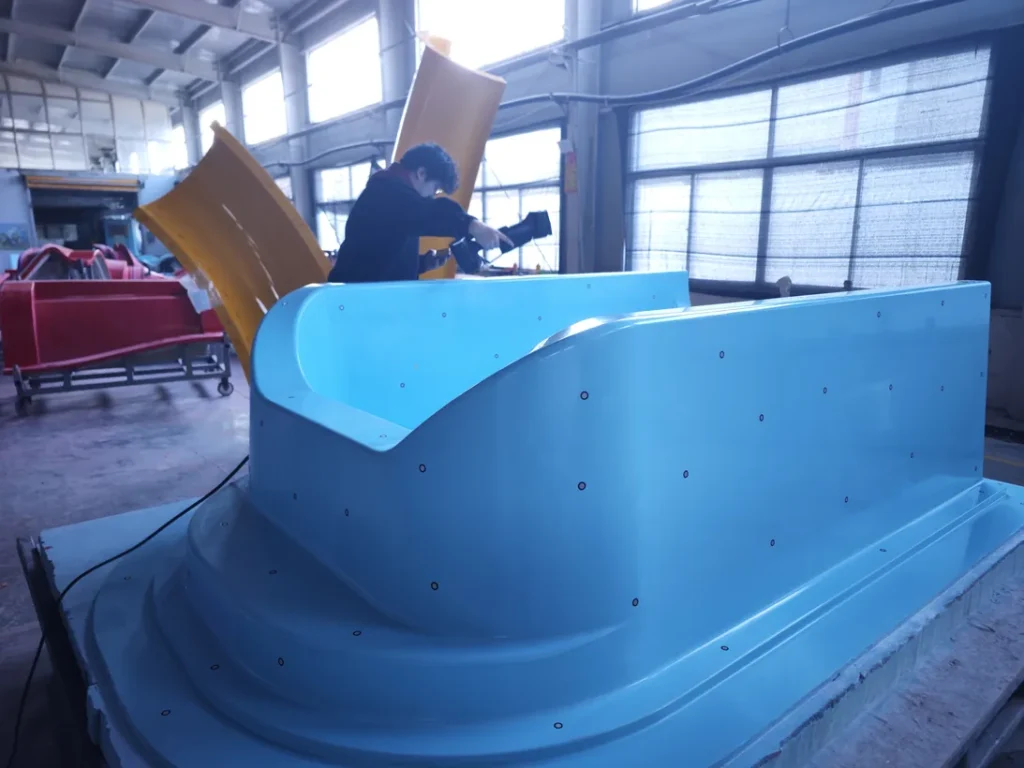
- Deployment: Markers are distributed across the target object, fixturing, or scanning environment in an evenly spaced, non-occluded pattern. Density is calibrated to the scanning system's field of view, with sufficient overlapping coverage across adjacent scan frames to support reliable registration.
- Detection: The scanning system's imaging sensors (cameras, laser detectors) capture light reflected or emitted by the markers, using edge detection, thresholding, or AI-powered pattern recognition to distinguish markers from background surface texture, ambient light, or measurement noise. Retroreflective markers are engineered to reflect light directly back to the system's light source, improving detectability at long ranges or in high-ambient-light conditions.
- Registration and Tracking: For static scanning workflows, detected markers present in overlapping scan frames are used to compute 6-degree-of-freedom (6DoF) transformation matrices that align all discrete frames into a single unified 3D point cloud. For dynamic scanning or tracking workflows, markers are used to calculate the real-time position and orientation of the scanner or target object relative to a fixed coordinate system. Projected virtual markers operate on the same core principle, but are emitted by dedicated projection hardware rather than applied as physical targets, eliminating contact with the target surface.
Key Parameters and Criteria
The performance and suitability of 3D scanning reference markers are evaluated against standardized measurable parameters, with selection criteria dependent on scanner hardware specifications, target object characteristics, and scanning environment conditions.
| Parameter | Meaning | Judgment Method |
|---|---|---|
| Marker Diameter | Physical size of the marker's active high-contrast detection area, measured across its longest axis | Matched to the scanning system's minimum resolvable feature size at the intended working distance; smaller diameters are used for close-range fine scanning, while larger diameters support long-range or large-volume workflows |
| Contrast Ratio | Ratio of light reflectivity between the marker's high-reflectance foreground and low-reflectance background regions | Measured under the scanning system's operating light conditions; values above 70% are standard for general industrial use, with retroreflective markers offering ratios exceeding 500% for high-ambient-light or long-range applications |
| Coding Capacity | For coded markers, the total number of unique identifiable patterns supported by the marker's design | Calculated based on the number and arrangement of pattern elements (e.g., dot grids, ring segments); higher capacity is required for large-volume scanning or multi-session workflows to avoid duplicate marker IDs |
| Adhesion Strength (Physical Markers Only) | Force required to remove a physical adhesive marker from a target surface, measured in Newtons per square centimeter | Selected based on target surface material, texture, and post-scanning processing requirements; low-adhesion variants are used for delicate or finished surfaces to avoid residue or damage, while high-adhesion variants are used for rough or porous surfaces |
| Localization Accuracy | Maximum positional deviation between the marker's detected center coordinate and its calibrated physical center | Verified by comparing marker positions measured by the 3D scanning system against a traceable calibrated coordinate measuring machine (CMM) reference |
Suitable and Unsuitable Scenarios
Suitable Scenarios
- Handheld 3D scanning of objects with low surface texture or uniform color, which lack natural features for reliable frame alignment
- Large-volume or multi-session scanning of large workpieces where consistent coordinate alignment across extended time periods or work shifts is required
- High-accuracy dimensional inspection workflows where registration error must be minimized to meet strict tolerance requirements
- Scanning of moving or dynamically positioned objects, where markers mounted on the object or fixturing enable real-time position tracking
- Delicate or high-value surfaces that cannot be modified with physical markers, where projected reference markers are a viable alternative
Unsuitable Scenarios
- Markerless optical tracking systems designed for rapid, non-contact scanning of high-texture objects, where markers add unnecessary preparation time
- Scanning of objects with very small surface areas or fine critical geometric features, where physical markers would occlude key measurement regions
- Surfaces with high porosity, high flexibility, or aggressive release agents that prevent physical markers from adhering consistently
- Workflows where post-scanning physical marker removal would damage finished surfaces, leave residue, or violate regulatory requirements, and projected markers are not available
Common Misconceptions
- Misconception: More markers always produce higher scanning accuracy. Correction: Excessive markers increase preparation time and can introduce occlusion of critical object features. Optimal marker density is determined by the scanner's field of view and alignment algorithm capabilities, with evenly spaced, non-overlapping markers delivering the most reliable results.
- Misconception: All reference markers are compatible with all 3D scanning systems. Correction: Marker size, contrast, and coding format are calibrated to specific scanner hardware (e.g., camera resolution, light wavelength, working distance); using non-specified markers can lead to detection failures or reduced registration accuracy.
- Misconception: Physical reference markers are the only valid type of alignment target. Correction: Projected virtual markers, natural feature tracking, and environment-mounted reference targets are all validated alignment methods suitable for specific use cases, such as scanning delicate surfaces or high-throughput automated workflows.
- Misconception: Marker placement has no impact on overall scanning workflow efficiency. Correction: Poor marker placement (e.g., clustered, occluded, or inconsistently spaced) can require manual rework during point cloud alignment, increasing post-processing time and reducing overall throughput.
Related Concepts
- Markerless 3D Scanning: A scanning approach that uses natural surface features, texture, or structured light patterns instead of dedicated reference markers for frame alignment and spatial tracking, suited for high-texture objects or rapid scanning workflows.
- Point Cloud Registration: The process of aligning multiple discrete 3D scan frames into a single unified coordinate system, which relies on reference markers, natural features, or external tracking hardware to compute 6DoF transformation matrices.
- Optical Tracking System: A measurement system that uses cameras to track the position and orientation of targets (including reference markers) in 3D space, used to support handheld scanning, robotic scanning, and dynamic measurement workflows.
- Projected Reference Targets: Temporary virtual markers projected onto target surfaces via laser or structured light projection hardware, eliminating the need for physical marker application and removal on delicate or high-value parts.
- Volume Accuracy: A key performance metric for 3D scanning systems, describing the maximum measurement deviation across a defined scanning volume, which is directly impacted by reference marker localization accuracy and registration quality.
FAQ
How do I select the correct marker size for my scanning workflow?
Marker size is primarily determined by your scanning system's working distance and minimum resolvable feature size. For close-range fine scanning (working distances under 500mm), smaller markers are suitable. For long-range or large-volume scanning (working distances over 1000mm), larger markers are required for consistent detection. Always refer to your scanning system's official specifications for recommended marker size ranges.
Can I reuse physical reference markers?
Most non-adhesive physical markers (e.g., machined metal markers mounted on fixturing) are fully reusable across multiple scanning sessions, provided they remain undamaged and free of contamination. Disposable adhesive markers are generally single-use, as removal can damage their contrast layer or leave adhesive residue that reduces adhesion in subsequent uses.
Do reference markers affect the final accuracy of my 3D scan?
Yes, reference marker localization accuracy directly impacts the overall registration accuracy of the final point cloud. Errors in marker position detection (caused by low contrast, damage, or incorrect size) propagate across aligned scan frames, leading to increased volume measurement deviation. Using calibrated, system-compatible markers minimizes this source of error.
What is the difference between coded and uncoded reference markers?
Uncoded markers have a uniform, patternless design and are used for local alignment of overlapping scan frames, as they cannot be uniquely identified across large scenes. Coded markers include a unique geometric pattern that assigns each marker a distinct ID, enabling unique identification across large volumes or multi-session workflows without requiring overlapping frame alignment for ID matching.
Summary
3D scanning reference markers are standardized visual targets that enable consistent spatial coordinate alignment, frame registration, and position tracking across industrial 3D scanning workflows. Available in physical and projected formats, their performance is evaluated against measurable parameters including size, contrast, localization accuracy, and coding capacity, with selection dependent on scanner hardware, target object characteristics, and workflow requirements. While critical for many high-accuracy and large-volume scanning applications, markers are not suitable for all use cases, with markerless tracking and projected targets offering viable alternatives for specific scenarios. Proper selection and deployment of reference markers are key to minimizing registration error and ensuring reliable, repeatable 3D measurement results.
- What Is 3D Scanning? Principles, Workflow, and Industrial Applications 3D scanning is a digital measurement technology that converts the surface geometry of physical objects into 3D data. This entry covers its working principles, core parameters, industrial use cases, common misconceptions, and related technical…
- What Is a 3D Scanner? Types, Parameters, and Selection Criteria A 3D scanner captures three-dimensional surface data from physical objects and converts geometry, dimensions, and features into digital data for inspection, reverse engineering, and modeling.
- What Is 3D Scanning Accuracy? Accuracy, Repeatability, and Resolution Explained 3D scanning accuracy describes how closely scan data matches an object's actual geometry and dimensions. It is assessed through local accuracy, volumetric accuracy, stitching accuracy, repeatability, and resolution.
- What Is Point Cloud Data? Point Clouds, Meshes, and CAD Models in 3D Scanning Point cloud data is an important raw data format in 3D scanning. It consists of discrete 3D coordinate points that describe object surface geometry and support inspection, reverse engineering, modeling, and archiving.
Hangzhou Insvision Technology Co.,Ltd.
Address: Building 1, No. 1399 Liangmu Road, Yuhang District, Hangzhou, Zhejiang 311121, China