
3D Mesh Model
A 3D mesh model is a digital representation of a physical object’s external surface, constructed from interconnected geometric primitives: vertices.
Definition
A 3D mesh model is a digital representation of a physical object’s external surface, constructed from interconnected geometric primitives: vertices (discrete 3D coordinate points), edges (connections between adjacent vertices), and faces (closed polygonal surfaces, most commonly triangles or quadrilaterals). In industrial 3D scanning workflows, mesh models are derived from raw point cloud data captured by 3D scanning hardware, and preserve the dimensional, spatial, and geometric characteristics of the scanned object for use in downstream engineering, manufacturing, and quality control processes.
How It Works
The generation of a 3D mesh model from physical objects follows a standardized workflow in industrial 3D scanning:
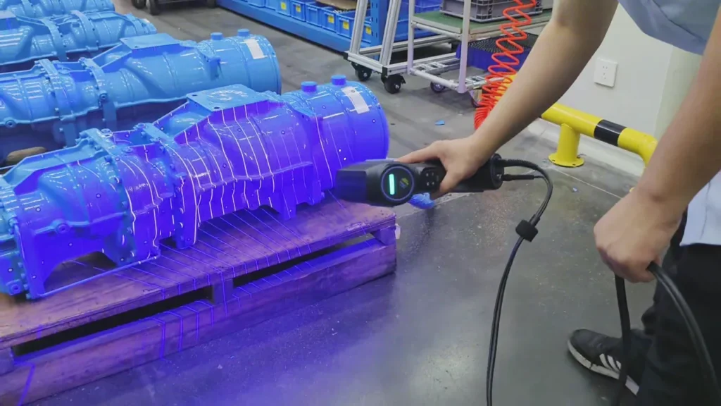
- Raw Data Acquisition: 3D scanning hardware (including structured light systems, handheld laser scanners, and optical tracking setups) captures millions of individual 3D coordinate points across the object’s surface, forming a raw point cloud. Capture quality depends on hardware specifications, object material, surface finish, and environmental conditions.
- Point Cloud Preprocessing: Raw point clouds are cleaned to remove noise, outliers, and redundant data points. Multiple scans of the same object from different angles are aligned (registered) into a single unified point cloud using common reference markers or feature matching.
- Meshing: Specialized algorithms analyze the spatial relationships between adjacent points in the cleaned point cloud to connect points into edges, then edges into closed polygonal faces. Triangular meshes are the most common output for industrial scanning due to their broad compatibility, while quad meshes may be generated for CAD-focused reverse engineering workflows.
- Mesh Post-Processing: Raw meshes are refined to address gaps, fill holes caused by un-scanned surface areas, correct face normal orientation, and adjust polygon density. Modern 3D processing software may leverage AI-powered algorithms to automate these steps, reducing manual work while preserving dimensional accuracy.
Key Parameters and Criteria
Mesh quality is evaluated against measurable parameters, with optimal values varying based on scanning hardware, object size, intended use case, and industry tolerance requirements. The following are core parameters for industrial 3D mesh models:
| Parameter | Meaning | Judgment Method |
|---|---|---|
| Dimensional Deviation | The degree of variance between the mesh’s measured dimensions and the physical object’s actual dimensions, or a reference CAD model | Align the mesh to a calibrated reference artifact or official CAD model; compute average and maximum deviation across a statistically significant sample of surface points |
| Vertex Count | The total number of discrete 3D coordinate points that form the base of the mesh structure | Automated count output by 3D processing software; higher counts indicate finer captured surface detail, with corresponding larger file sizes |
| Face Count | The total number of closed polygonal surfaces making up the mesh, most commonly triangular for scanning outputs | Automated count in mesh analysis tools; aligned to use case (e.g., fine-feature inspection requires higher face counts than basic visualization) |
| Watertightness | The state of the mesh being a fully closed solid volume with no unclosed edges, overlapping faces, or gaps | Automated validation tools in 3D software that flag open edges, non-manifold geometry, or unconnected surface segments |
| Polygon Aspect Ratio | The ratio of the longest edge to the shortest edge of an individual mesh face | Automated analysis in mesh processing tools; ratios closer to 1:1 indicate more uniform, higher-quality geometry that performs better in downstream processing |
Suitable and Unsuitable Scenarios
Mesh models are tailored to specific industrial use cases, with clear boundaries for appropriate application.
Suitable Scenarios
- Reverse engineering of mechanical components, tools, and molds where original design data is unavailable
- Dimensional quality inspection and GD&T analysis of production parts against reference CAD models
- 3D printing prototype preparation and custom manufacturing workflows
- Digital asset creation for automotive interior customization, aerospace part digitization, and energy component documentation
- Tool and mold repair validation, where mesh models are used to compare worn parts to original design specifications
Unsuitable Scenarios
- Applications requiring internal volumetric structural data, as meshes only represent external surface geometry
- Ultra-high-precision metrology of sub-micron features that fall outside the accuracy range of the scanning hardware used to generate the mesh
- Real-time dynamic material deformation simulation, which requires additional finite element modeling (FEM) data not embedded in standard mesh files
- Workflows requiring fully editable parametric CAD geometry, as meshes require additional reverse engineering steps to convert to feature-based CAD formats
Common Misconceptions
- Misconception: 3D mesh models are identical to parametric CAD models
Clarification: Mesh models are polygon-based surface representations, while parametric CAD models are feature-editable, dimension-driven solid models. Scanned meshes require dedicated reverse engineering workflows to convert to fully editable parametric CAD files.
- Misconception: Higher vertex or face count always produces a higher-quality mesh
Clarification: Excessively high polygon counts increase file size and processing time without functional benefit for use cases such as basic visualization or large-part prototyping. Optimal mesh density is matched to the specific requirements of the intended application.
- Misconception: All scanned meshes are ready for 3D printing without additional processing
Clarification: 3D printing requires meshes to be watertight, free of non-manifold edges, and have consistent face normals. Raw scanned meshes often have gaps, misaligned normals, or overlapping faces that require post-processing to meet 3D printing requirements.
- Misconception: 3D scanning produces a finished mesh with zero user input
Clarification: Raw point cloud data requires preprocessing to remove noise and align multiple scans, and initial meshes often require refinement to fill gaps from un-scanned surface areas. While modern software automates many of these steps, complex or high-accuracy use cases may require manual adjustment by trained operators.
Related Concepts
- Point cloud: Raw unstructured 3D coordinate data captured by 3D scanners, used as the input for mesh generation
- Reverse engineering: The workflow of recreating design data for physical parts, which uses high-precision meshes as a core input
- Dimensional deviation analysis: The quality control process of comparing mesh models to reference CAD files to identify production defects
- Parametric CAD model: Feature-based, editable digital solid model, often derived from scanned meshes via reverse engineering
- 3D metrology: The field of precision industrial measurement, which uses calibrated mesh models for part inspection and validation
- Structured light scanning: A 3D scanning technology that uses projected light patterns to capture point cloud data for mesh generation
- Optical tracking: A system that monitors scanner position and orientation in 3D space to enable accurate point cloud alignment for large or complex objects
FAQ
What is the difference between a triangular mesh and a quad mesh?
Triangular meshes are the most common output of industrial 3D scanning, using three-sided polygons to form surfaces. They offer fast processing, broad compatibility with inspection and 3D printing tools, and strong performance for representing complex curved or organic surfaces. Quad meshes use four-sided polygons, which are easier to edit in CAD software and better suited for reverse engineering workflows that require conversion to parametric models.
Can a 3D mesh model be used directly for GD&T inspection?
Yes, when generated from calibrated, metrology-grade scanning hardware and processed with industrial 3D metrology software, high-precision mesh models aligned to a standard reference coordinate system can be used for full GD&T (geometric dimensioning and tolerancing) analysis. Mesh accuracy must be calibrated to meet the tolerance requirements of the specific inspection use case.
How do I adjust mesh density for different use cases?
Mesh density, controlled by vertex and face count, is adjusted during post-processing. High-density meshes with a high polygon count are used for fine-detail inspection or reverse engineering of small, complex parts, while simplified low-density meshes are preferred for visualization, large-part prototyping, or applications where small file size is a priority. Most 3D processing tools include automated simplification and refinement functions that adjust density without losing critical dimensional accuracy.
Why do some scanned meshes have holes or gaps?
Holes or gaps in scanned meshes typically result from areas of the physical object that the scanner could not fully capture, such as deep cavities, highly reflective or transparent surfaces, or areas blocked by obstructions during scanning. Small gaps can be filled via automated algorithms in 3D processing software, while large or complex gaps may require additional targeted scanning of the missing surface areas to maintain dimensional accuracy.
Summary
A 3D mesh model is a polygon-based digital surface representation of a physical object, serving as a core output of industrial 3D scanning workflows. Generated from raw point cloud data via standardized preprocessing, meshing, and post-processing steps, mesh quality is evaluated via measurable parameters including dimensional deviation, watertightness, and polygon density. Meshes support a wide range of industrial use cases from reverse engineering to dimensional quality inspection, though they require alignment to specific workflow requirements and targeted post-processing to address limitations such as un-scanned gaps or excess polygon count.
- What Is 3D Scanning? Principles, Workflow, and Industrial Applications 3D scanning is a digital measurement technology that converts the surface geometry of physical objects into 3D data. This entry covers its working principles, core parameters, industrial use cases, common misconceptions, and related technical…
- What Is a 3D Scanner? Types, Parameters, and Selection Criteria A 3D scanner captures three-dimensional surface data from physical objects and converts geometry, dimensions, and features into digital data for inspection, reverse engineering, and modeling.
- What Is 3D Scanning Accuracy? Accuracy, Repeatability, and Resolution Explained 3D scanning accuracy describes how closely scan data matches an object's actual geometry and dimensions. It is assessed through local accuracy, volumetric accuracy, stitching accuracy, repeatability, and resolution.
- What Is Point Cloud Data? Point Clouds, Meshes, and CAD Models in 3D Scanning Point cloud data is an important raw data format in 3D scanning. It consists of discrete 3D coordinate points that describe object surface geometry and support inspection, reverse engineering, modeling, and archiving.
Hangzhou Insvision Technology Co.,Ltd.
Address: Building 1, No. 1399 Liangmu Road, Yuhang District, Hangzhou, Zhejiang 311121, China