

What a Handheld 3D Scanner Does in Industrial Manufacturing and Inspection
Learn how INSVISION handheld 3D scanners capture dense surface geometry for mold inspection, large welded assemblies, and forging wear analysis. See how laser modes and tracking support real manufacturing tasks.
A handheld 3D scanner is used in industrial work to capture complete surface geometry as dense, measurable 3D data, turning a physical workpiece into a digital model for inspection, reverse engineering, wear assessment, or archival. The core value is direct access: instead of repositioning a fixed measuring arm or trying to reach an internal cavity with calipers, the operator moves the scanner around the part and collects continuous surface information. The right equipment choice is therefore driven by the workpiece itself. A large welded assembly needs a different acquisition strategy than a small mold insert with a deep cavity, and the scanner's laser configuration, working distance, and positioning method should match that access problem. INSVISION handheld 3D scanners address these tasks by combining configurable laser modes with marker-based or tracking-based positioning, so the acquisition method follows the geometry rather than forcing the part to fit a fixed measurement setup.
Common industrial tasks solved by handheld 3D scanners
Handheld scanning earns its place where traditional measurement becomes slow or incomplete. In mold manufacturing, an extrusion die for a refrigerator heat-dissipation plate can develop internal wear that a caliper cannot reach; the INSVISION AlphaScan handheld scanner records the worn cavity surface so the change can be quantified against a known reference. For machined parts, the same approach supports quality inspection when multiple curved features, bores, and edge transitions must be checked together rather than point by point. In steel production, a qualified cold roll can be scanned with AlphaScan to establish a baseline, and a roll in service can then be compared to that baseline to identify localized wear.
The same principle extends to much larger workpieces. Large welded structures in heavy machinery, shipbuilding, or rail applications are difficult to measure because their dimensions exceed the reach of a conventional measuring arm. A tracking-based handheld system changes the workflow by locating the scanner in space during acquisition, so the operator can move around the part and collect features such as weld seams, rib gaps, and deep sections without stopping to reposition a fixed measurement setup.
Cultural heritage projects use handheld scanning on a different scale of access problem: a 16-meter-long, 3-meter-high memorial screen wall with relief carving and inscriptions can be recorded non-contact to create a durable digital archive for conservation, research, or virtual display.
How scanner capabilities match different job requirements
Capability selection starts with the geometry that must be captured. The AlphaScan handheld scanner offers a precision mode with 7 blue laser lines for detailed surface work, a deep-hole mode with a single blue laser line for narrow access, and a working distance of 300 mm with a 200 mm fine mode. Its scanning area reaches up to 650 mm × 550 mm, which suits parts where the operator needs a balance between local detail and efficient coverage.
For faster data collection on complex parts, the AlphaScan Elite S1 adds a high-speed mode with 50 blue laser lines, a measurement rate of 8,100,000 measurements/s, and an intelligent hole-rescanning mode that identifies holes and cut edges during acquisition. These modes matter when a part combines large surfaces with many openings or cut features that would otherwise be missed in a single pass.
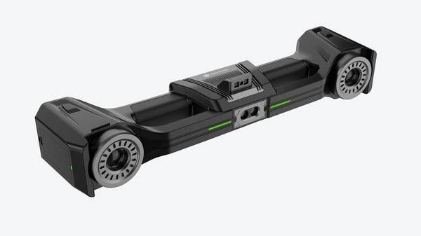
When the workpiece is a large welded structure or another oversized assembly, the acquisition problem shifts from local detail to stable positioning across a wide area. The V-Track tracking-based laser 3D scanning system uses an optical tracker to locate the handheld scanner continuously, eliminating the need to place markers across the entire surface. Because the scanner position is established in a single coordinate system during acquisition, the operator can cover large features without stopping to build marker networks or re-register separate measurement stations. The system provides a maximum scan area of 2600 × 2200 mm, which reduces the number of passes needed on large weldments while still producing a full-surface mesh for dimensional analysis.
How a typical handheld scanning workflow delivers usable data
A useful handheld scanning workflow begins with preparation that supports reliable alignment. On a forging anvil with a V-shaped groove, for example, the operator clears debris and ash from the work area, ensures power is available, and selects scan positions that cover the V-groove, edges, and regions where deformation or cracking is likely. With the AlphaVista, surface markers are applied so that the scanner can establish the workpiece's position and coordinate system before the main scan begins. The operator then scans the marked surface to determine relative coordinates and position, after which surface acquisition can proceed.
After acquisition, the scan data is processed into a 3D mesh model. That model becomes the basis for comparison against a reference model or an earlier baseline, allowing the team to quantify deformation, cracking, assembly deviation, or dimensional error. In the forging anvil case, the scanned model is compared with the original standard model to analyze changes in the V-shaped working surface, and the result is exported for further processing and storage. For a large welded structure, the exported STL model is aligned to the CAD design for full-surface deviation analysis, producing a color map that shows where the part departs from nominal geometry.
The final deliverable is not merely a point cloud; it is a measurable record that supports repair decisions, process adjustment, or long-term dimensional archiving.
Hangzhou Insvision Technology Co., Ltd.
Address: Building 1, No. 1399 Liangmu Road, Yuhang District, Hangzhou, Zhejiang 311121, China
Copyright © Hangzhou Insvision Technology Co., Ltd. All rights reserved.
Copyright © Hangzhou Insvision Technology Co., Ltd. All rights reserved.